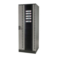
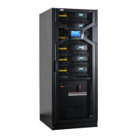
Figure 10: Front view of the Conceptpower DPA 500 frame, left side with closed doors and on the right side
with open doors and bottom front plate removed.
1 Active sub-modules
2 Passive sub-modules
3 System display
4 Door handles
5 Module-dedicated battery breakers (F3-1, F3-2, F3-3, F3-4, F3-5) 4x125 A / 600-800 VDC
6 Module-dedicated bypass fuses (F2-1, F2-2, F2-3, F2-4, F2-5) 3x160 A gG/gL – NH00
7 Module-dedicated output breakers (IA2-1, IA2-2, IA2-3, IA2-4, IA2-5) manual switch
8 Slot for
SNMP or modem cards
9 Customer interface
10 Parallel interface
11 Spot for the Maintenance Bypass Switch – MBS (optional)
12 I/O connection terminals

 Loading...


