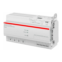
Current Sensors
The menu allows to have access to the information briefly listed below together with the buttons you
can use. It is possible to use Selection Filter and Sort Function on Phase, Node and Group labels to find
desired values. It is also possible to add new sensors by own defined ID number, to change the ID number
and to set a LED off timeout if desired.
Buttons
Add
Add and assign new
current sensor
Create a new sensor ID and then assign it to the physical sensor by
clicking the pushbutton of the sensor (Note: Wait for confirmation
before assigning the next sensor)
Assign current sensor
(already added)
If a sensor ID has already been created but is unassigned, it is here
possible to assign it to the physical sensor by clicking the pushbutton
of the sensor.
Add new current
sensor (no assigning)
Create a new branch ID without assigning it to the physical
sensor.
Identify
Clicking the pushbutton of the current sensor allows to display
the sensor ID number.
Change ID
Select the current ID number of the current sensor and define the
new ID number of it.
Remove all
Remove all sensors and their settings.
To remove one single sensor click on the “X” symbol under the
Action column
Sensors Definitions
ID Sensor identification number (at this time it cannot be modified)
Phase
Selects the corresponding sensor phase for the calculation of
sensor active power and energy.
It is possible to choose:
- L1, L2, L3, N for alternate current measurements
- DC for direct current measurements.
Node
Defines the node in which the sensor is assigned in the “Tree
view” configuration. It is automatically filled once the sensor is
configured in the “Tree view” page
Group
Defines the group in which the sensor is added in the “Groups”
configuration. It is automatically filled once the sensor is added in
the “Groups” page
Name
Defines the name of the sensor. It must be unique and can be
composed by up to 64 characters
Power Factor
Defines which power factor shall be used for calculation:
AUTO - uses the Power Factor of defined mains phase
x.xx - you can manually define a constant power factor (e.g. 0.85)
0 - type zero for changing from manual to auto power factor
Action Remove the single sensor
[Click a row]
By clicking a row, the row is highlighted in light blue and the
corresponding box is checked. Additionally the LED of the
selected sensor will start to blink.
After removing checkboxes row is not highlighted anymore.
Make sure to select the correct phase on which the current sensor is installed in the phase column.
If needed, change the Power Factor (PF) from Auto to a manual value corresponding to the PF of the
measured load.
SCU100 INSITE PRO M COMPACT USER MANUAL 37

 Loading...