Axis 1
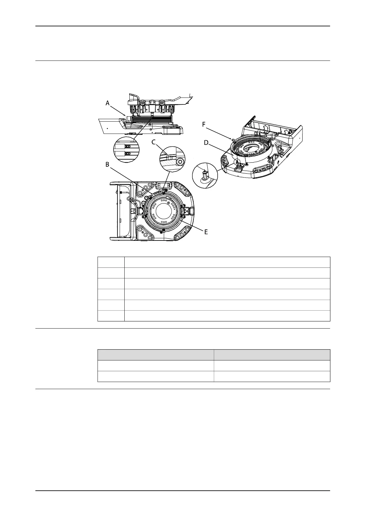
The illustration below shows the position switch for axis 1. The switch is connected
directly to the connector in the base, R1.SW1.
xx0100000158
Position switch, axis 1A
CamB
Set screw, cam (cam stop)C
Protection sheetD
RailE
Rail attachmentF
Specifications
Maximum voltage/current for the position switches:
ValueParameter
Max. 50 VDCVoltage
Max. 1 ACurrent
Connections
The position switch is connected to different points on the robot system:
• XT8, screw terminal in the controller cabinet when position switch cables are
used.
• R1.SW1 at the robot base. Customer connection set is recommended. Art.no.
is specified in Required equipment on page 81.
Further information about cables and connection points, see section Robot cabling
and connection points on page 88.
Continues on next page
82 Product manual - IRB 660
3HAC025755-001 Revision: W
© Copyright 2006-2020 ABB. All rights reserved.
2 Installation and commissioning
2.4.4 Installation of position switch, axis 1 (option)
Continued