Im(Y
o)
Re(Yo)
Circle radius
OPERATEOPERATE
OPERATE OPERATE
Im(Yo)
Re(Y
o)
Circle radius
OPERATEOPERATE
OPERATE OPERATE
Circle conductance
Circle susceptance
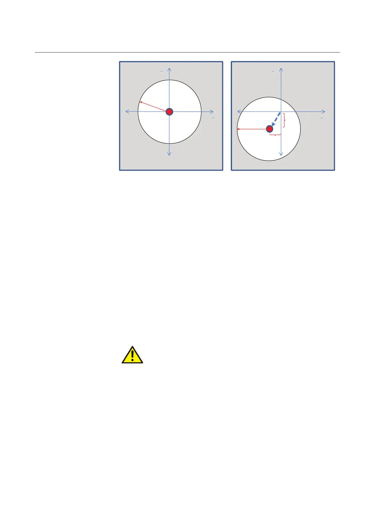
GUID-AD789221-4073-4587-8E82-CD9BBD672AE0 V1 EN
Figure 162: Overadmittance characteristic. Left figure: classical origin-centered
admittance circle. Right figure: admittance circle is set off from the
origin.
Non-directional overconductance characteristic
The non-directional overconductance criterion is enabled with the Operation mode
setting set to "Go" and Directional mode to "Non-directional". The characteristic is
defined with two overconductance boundary lines with the Conductance forward
and Conductance reverse settings. For the sake of application flexibility, the
boundary lines can be tilted by the angle defined with the Conductance tilt Ang
setting. By default, the tilt angle is zero degrees, that is, the boundary line is a
vertical line in the admittance plane. A positive tilt value rotates the boundary line
counterclockwise from the vertical axis.
In case of non-directional conductance criterion, the Conductance reverse setting
must be set to a smaller value than Conductance forward.
Operation is achieved when the measured admittance moves over either of the
boundary lines.
The non-directional overconductance criterion is applicable in high-
resistance earthed and compensated networks. It must not be
applied in unearthed networks.
1YHT530004D05 D Section 4
Protection functions
615 series 325
Technical Manual
 Loading...


