T_F32_INT8
F32
INT8
TPOSSLTC
BI0
BI1
BI2
BI3
BI4
BI5
SIGN_BIT
TAP_POS
OLATCC
I_A
I_B
I_C
U_AB
TR1_TAP_POS
TR2_TAP_POS
TR3_TAP_POS
RAISE_LOCAL
LOWER_LOCAL
TAPCHG_FLLW
PARALLEL
AUTO
CON_STATUS
LTC_BLOCK
TCO
RSV
TR1_I_AMPL
TR1_I_ANGL
TR2_I_AMPL
TR2_I_ANGL
TR3_I_AMPL
TR3_I_ANGL
RAISE_OWN
LOWER_OWN
FLLW1_CTL
FLLW2_CTL
FLLW3_CTL
BLKD_I_LOD
BLKD_U_UN
BLKD_U_OV
BLKD_I_CIR
BLKD_LTCBLK
ALARM
PAR_FAIL
PARALLEL
AUTO
TIMER_ON
TR0_I_AMPL*
TR0_I_ANGL*
IL1b
IL2b
IL3b
U12b
BI6_AUTO
BI1_TCO
TAP_POS value is transferred from
TPOSSLTC to OLATCC automatically
PO2_RAISE_OWN
PO1_LOWER_OWN
TAP_POS
X130 (RTD).AI_VAL1
BI3_LOWER_LOCAL
BI4_RAISE_LOCAL
* Only for GOOSE Engineering
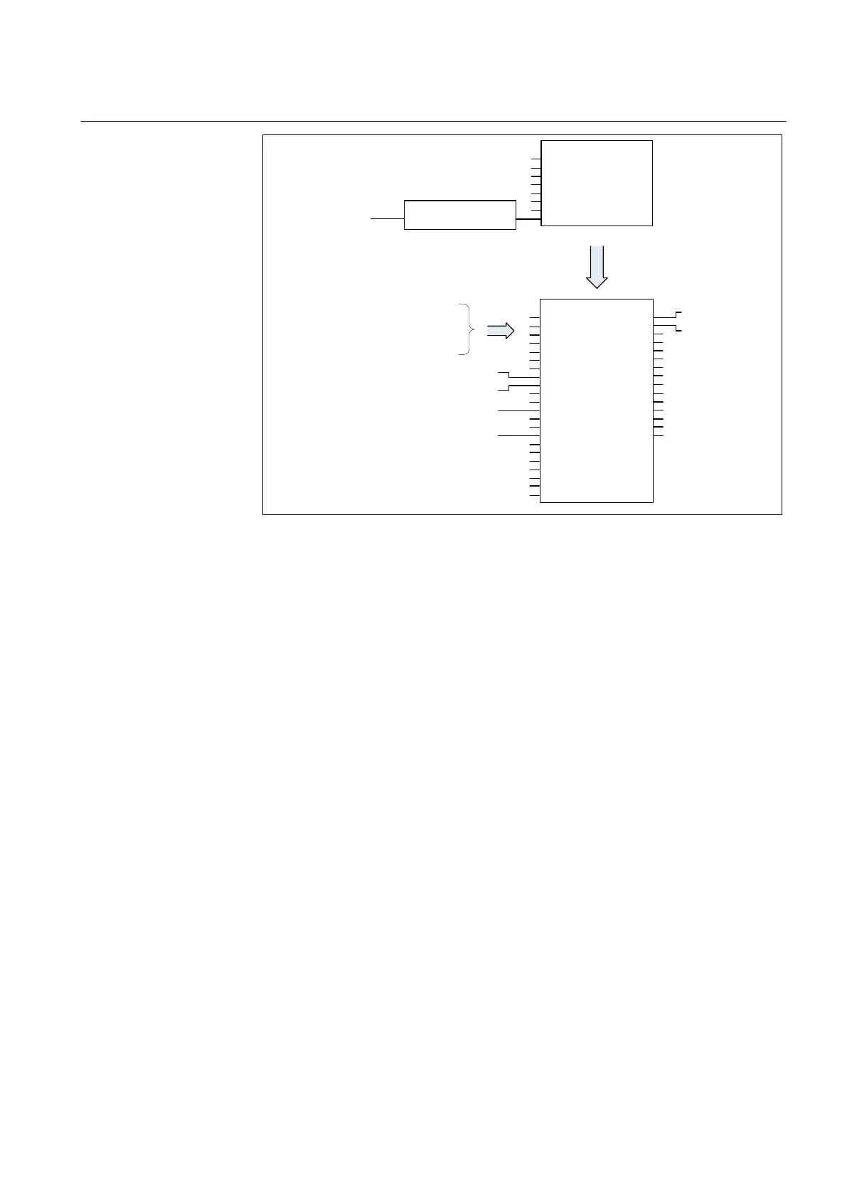
GUID-CA9CF06F-2ADB-4758-B527-EE4400B35B36 V2 EN
Figure 403: Configuration example for the Manual and Auto single modes
The configuration example uses an mA signal to indicate the current tap position of
the local transformer. To take that position information to OLATCC, the measured
mA signal is first scaled with the X130 (RTD) function. The scaled value is then
converted to integer value with T_F32_INT8 function. That integer value is
connected to the TAP_POS input of the TPOSSLTC function. The tap position
value is automatically transferred from TPOSSLTC to OLATCC without a
configuration connection.
Configuration example for the Auto parallel (Master/Follower) mode
The configuration example for Master/Follower describes how the tap position
information is transferred from follower to master with the horizontal GOOSE
communication. The status information from circuit breakers and an extra logic can
be used to change the operation mode via inputs of the master and the follower
(Operation mode = "Input control").
1YHT530004D05 D Section 9
Control functions
615 series 753
Technical Manual