ABEM Terrameter LS
41
position of the first electrode of the layout. The value entered should thus be the
number of electrode spacings from the first electrode to the Terrameter LS. For the
first station with the first cable excluded the value should therefore be at -20 to get the
start position of the pseudo section right. The second station should be at 0, the third
at 20 and so on. The station coordinates are automatically updated with the correct
step when doing roll-along, so if the first station coordinate is set correctly the rest
will follow.
5.2.4 Cable Exclusion
For a 4x21 take-out cable system “Cable 1” should be excluded at the first station, and
similarly “Cable 4“ should be excluded at the last station. This procedure is described
in section 6.5 “2D Electrical Imaging”.
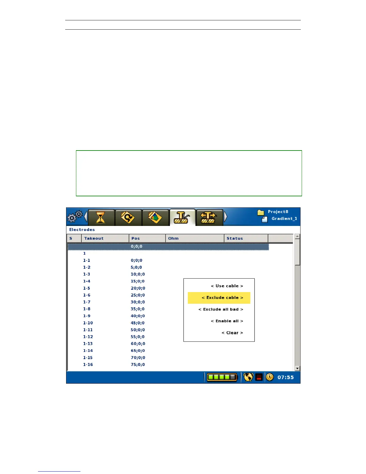
• Excluding a cable (also see Section 6.9.2 “Electrode Contact Test”)
― Move the highlight to the wanted cable
― Press <Options> and the option menu will be shown
― Highlight the <Exclude cable> Menu Item (Figure 44)
― Press <Ok>
Figure 44. Exclude cable pop-up menu