ABEM Terrameter LS
53
In this View the number of the measurement and key values for the transmitted signal
are displayed immediately below the header.
Note! The measurement number is not reset when creating a
new Task or switching between Tasks, it is incremented
continuously within a Project.
One measurement can have measurements for anything between one and twelve input
channels, plus the transmitter-monitoring channel (Tx).
The data for the measuring channels is displayed in a table showing channel number,
position of the electrodes used for that measurement (normally in the form cable#-
electrode#), measured quantity (delta voltage or current), normalised standard
deviation (variation coefficient), resistance, apparent resistivity, and, if applicable,
chargeability. There is a difference for the transmitter channel row where the output
voltage is shown in the resistance column.
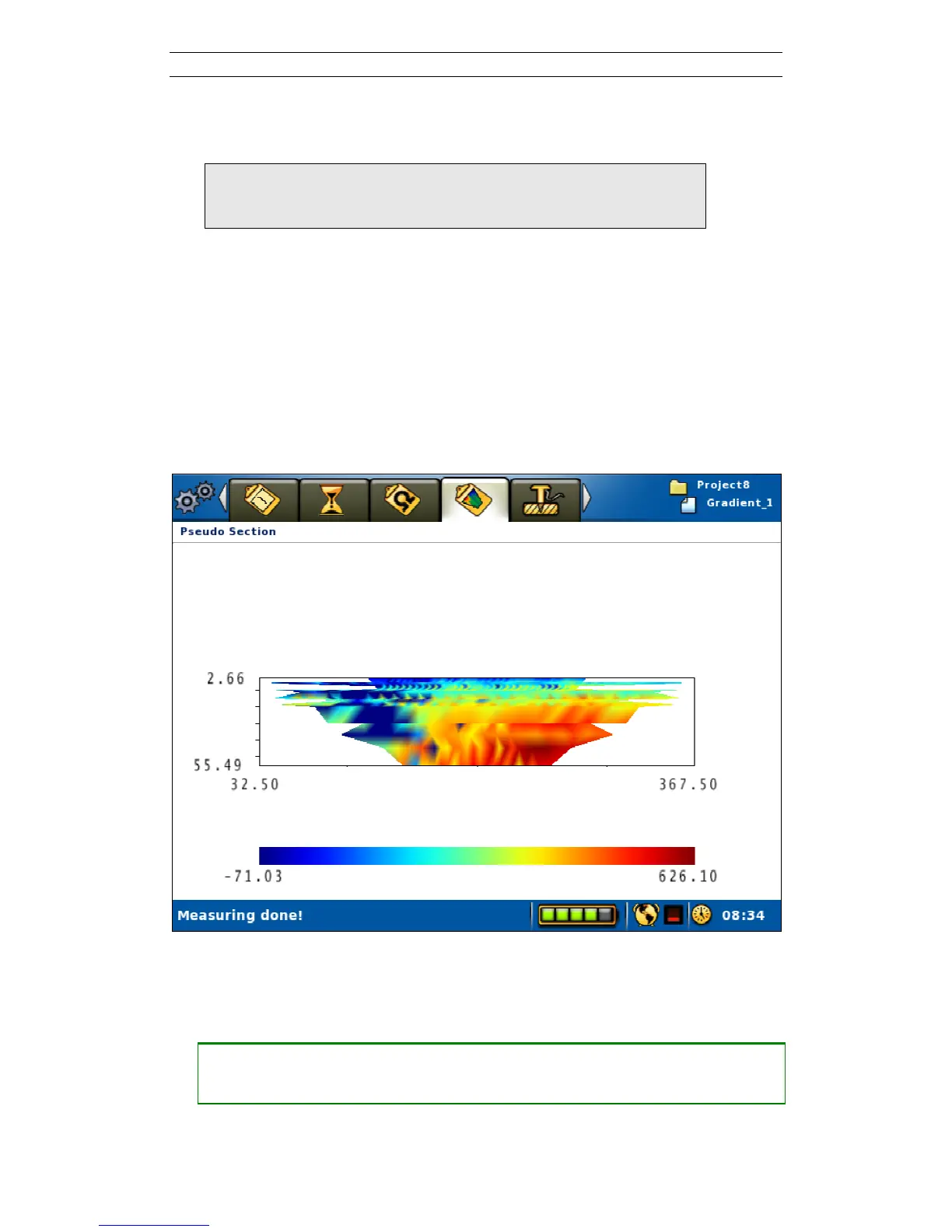
Another way to display the data on-line is in the form of a pseudo section as can be
seen on the “Measure/Pseudo Section” View (Figure 58).
Figure 58. Pseudo section view
6.9.4 Pausing / Stopping the Data Acquisition
• Pausing or stopping the measurement
― Move the highlight to the <Stop Measuring> row (Figure 55)
― Press <Ok>