| System installation – Electrical connection of the eMShome for indirect measurement with current transformers
12
Electrical connection of the eMShome for indirect measurement with current
transformers
Proceed as follows:
1 Mount the eMShome on a top-hat rail.
y Hook the eMShome onto the top edge of the
top-hat rail and press it until it clicks into place.
L1
L1 L2 L3
L1 L2 L3 N
L2 L3
N
L1 L2 L3
L1 L2 L3 N
I/s2
I/s2
I/s2
k/s1
k/s1
k/s1
eMS home
Consumer
Fuse
3×10/16A
Current
transformers
Circuit breaker
Electricity sup-
ply company’s
energy meter
Public electricity network 230/400V
Meter fuse 3×63 A
DANGER: see
note below
OUT
IN
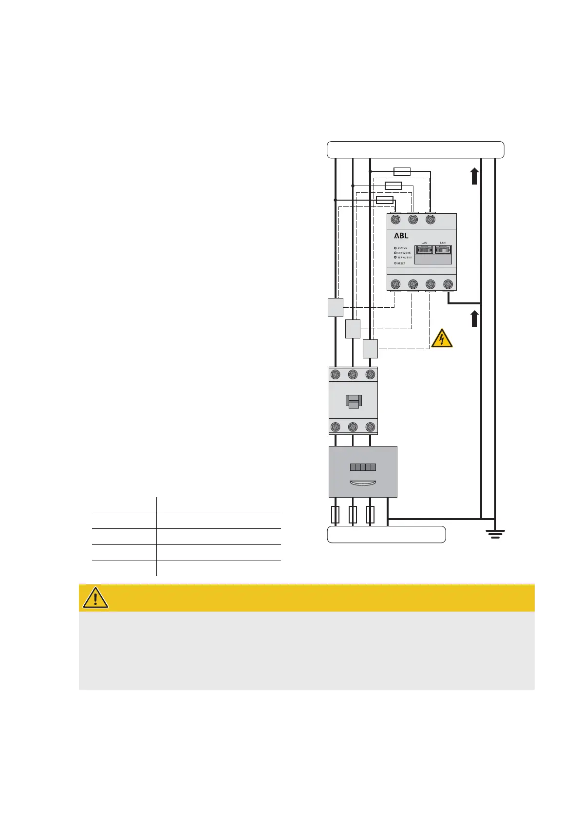
Example for implementation
2 Lead the outer conductors L1, L2 and L3 through one
current transformer each.
3 Connect a cable for the secondary current measure-
ment to each current transformer at terminals k/s1
and I/s2.
y Pay attention to the permissible connection cross
section of the eMShome (see “Technical specifi-
cations” onpage48).
4 Connect the connecting cables for the current meas-
urement to the eMShome (see also box below).
y Pay attention to the permissible tightening torque
for the screw terminals (see “Technical specifica-
tions” onpage48).
5 Connect the connecting cables for the voltage meas-
urement to the eMS home (see also box below).
y Pay attention to the permissible tightening torque
for the screw terminals (see “Technical specifica-
tions” onpage48).
6 Connect the connecting cables for the voltage meas-
urement to the outer conductors L1, L2 and L3.
Designation Explanation
L1, L2, L3 Outer conductor
N Neutral
OUT Meter output, consumer side
IN Meter input, mains side
WARNING!
Specifications for connecting two lines in one terminal
Please observe the following specifications for the connection cables for current and voltage measurement:
If the cross-sections of the two connection cables for current and voltage measurement differ (greater than
±0.5mm²), you should clamp these cables together in a suitable double-wire end sleeve.
It is not permitted to connect a stranded and a rigid cable together in one terminal.
 Loading...