System installation – Termination of the data lines |
15
Termination of the data lines
To ensure correct communication via the bus, the data line must be terminated at the RS485 connector of the
eMShome and at the Modbus interface of the last wallbox in the group installation. To this end, the eMShome is
supplied ex works with two terminating resistors and two jumpers, which are required for terminating the respective
interfaces.
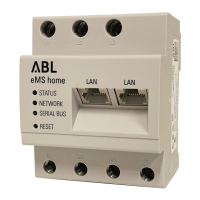
Termination at the eMShome
► Insert the enclosed terminating resistor between
test pins 3 and 4 on the RS485 connector of the
eMShome.
y Always keep a minimum distance of 10mm from
live parts.
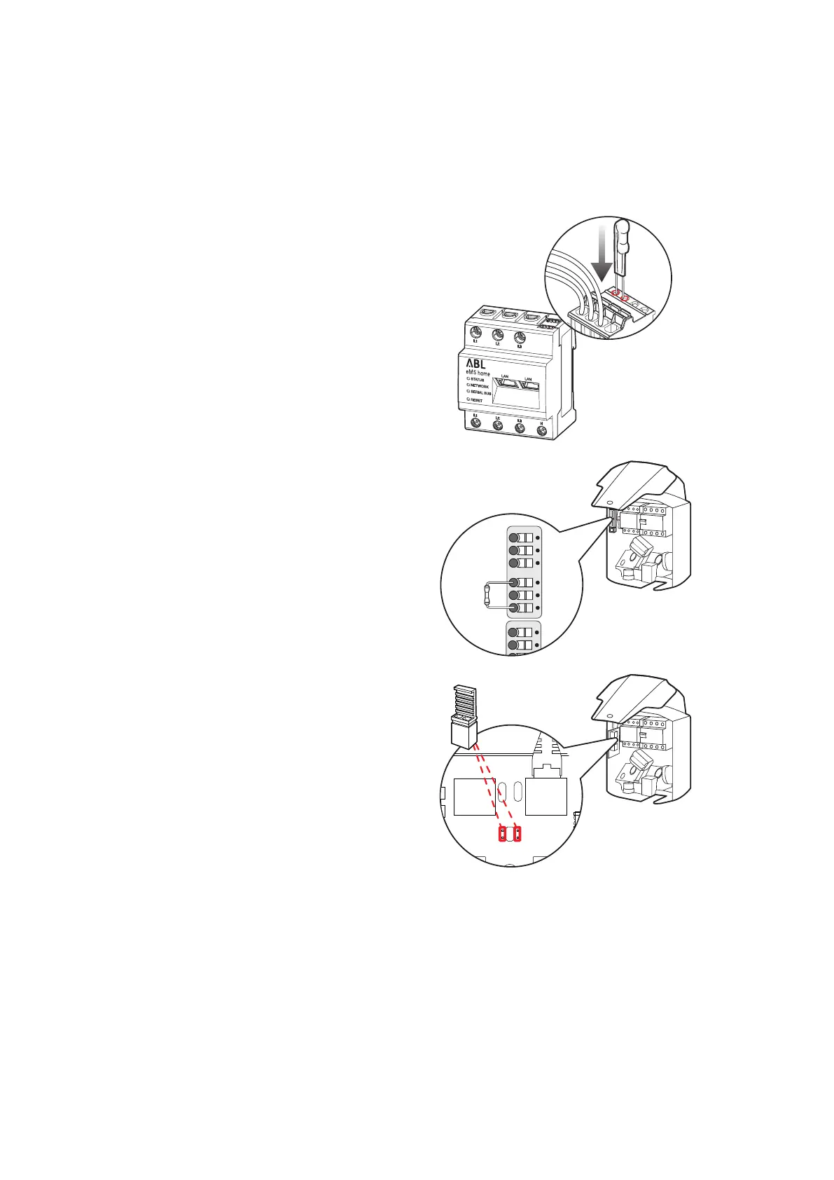
Termination of a wallbox with spring terminals
(eMH1 before mid-2021)
► Insert the enclosed terminating resistor in the spring
terminal which is not connected to the data lines,
between terminals A and B of evcc/rfid.
A M B
evcc/rfid
A M B
meter
A M B
meter
Termination of a wallbox with E2I interface
(eM1 from mid-2021)
► Connect the pin contacts of the E2I interface marked
CONTROL and METER using a jumper for each.
MODBUS
EN1
MODBUS
METER
M
E
T
E
R
C
N
T
R
L
CONTROL
CONTROL
METER
Setting up the wallboxes
To communicate with the eMShome, all wallboxes in the system must be set up individually and given their own
address. Setup and address assignment are carried out via the ABL Configuration Software, which is available for
download at https://www.ablmobility.de/en under Service > All downloads > Software > Configuration Soft-
ware. To do this, after completing the mechanical and electrical installation of the wallboxes, establish a data con-
nection between the computer on which the ABL Configuration Software is installed and the bus interface of the
wallboxes.
 Loading...