System installation – Bus wiring of the wallboxes and the eMShome |
13
DANGER!
Danger of death by electric shock at the current transformer terminals
The eMShome is supplied with warning stickers which advise the user to read these instructions and which
are intended to protect against electric shock and other hazards caused by high
currents.
Due to the type of connection, there is a mains voltage of 230V present at
conductors k/s1 and l/s2.
To prevent accidents, apply the warning stickers at this location on site.
WARNING!
Use of a meter fuse or circuit breaker
The end user must be able to isolate the eMShome from the power supply by means of a freely accessible meter
fuse or an additional circuit-breaker.
WARNING!
Note on the correct assignment of the phases
Make sure that the phases are each assigned correctly. Otherwise, the eMShome will provide incorrect meas-
ured values.
Bus wiring of the wallboxes and the eMShome
To control the charging currents, all wallboxes in the system must be wired via a data cable and each set up via the
ABL Configuration Software (see “Configuration via the ABL Configuration Software” onpage17 onwards).
Communication between the eMShome and the eMH1 Wallboxes is via CAT5e or
equivalent data lines, which must comply with the specifications in section “Data
cable recommendations” onpage49.
The data lines are connected to the internal spring terminals (for products manu-
factured before mid-2021) or via the E2I interface (for products manufactured from
mid-2021) on the inside left of the eMH1 housing (see next section).
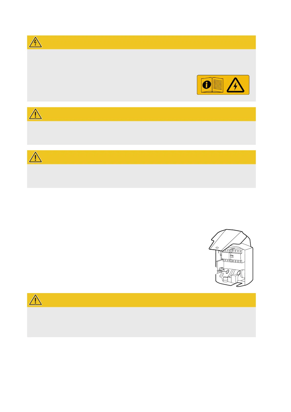
The data lines are fed in and out via the designated opening 1 in the rear shell of
the housing (see installation instructions for the eMH1 Wallbox).
The total length of the data lines within the group installation must not exceed
100m.
WARNING!
Important note on plugging in the RS485 connector in the eMShome
Please note that the RS485 connector may only be plugged into the eMShome after configuration in the ABL
Configuration Software (see page17 onwards): Otherwise, there may be problems with communication in
the system.
Bus wiring via spring terminals
For bus wiring via spring terminals (for products manufactured before mid-2021), the following generally applies:
The twisted wires of the data line must be connected to the contacts evcc/rfid A and evcc/rfid B of the wall-
boxes’ internal spring terminals.
1
 Loading...