| System installation – Bus wiring of the wallboxes and the eMShome
14
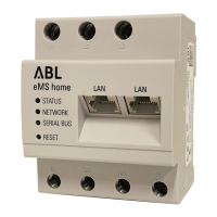
The colour assignment between the data lines and the contacts evcc/rfid A, evcc/rfid B and evcc/rfid M
on the spring terminals must be identical in every wallbox in the system and must not be changed under any
circumstances.
The data line from the previous wallbox is connected to the left spring terminal, and the data line for the follow-
ing wallbox is connected to the right spring terminal.
Connect the data line to the RS485 connector of the eMShome in such a way that it is assigned to the spring
terminal in the first wallbox as follows (see also “PIN allocation within the system” onpage49):
RS485 terminal (eMShome) eMH1 spring terminal
Pin 3 Pin A
Pin 4 Pin B
Pin 2 Pin M
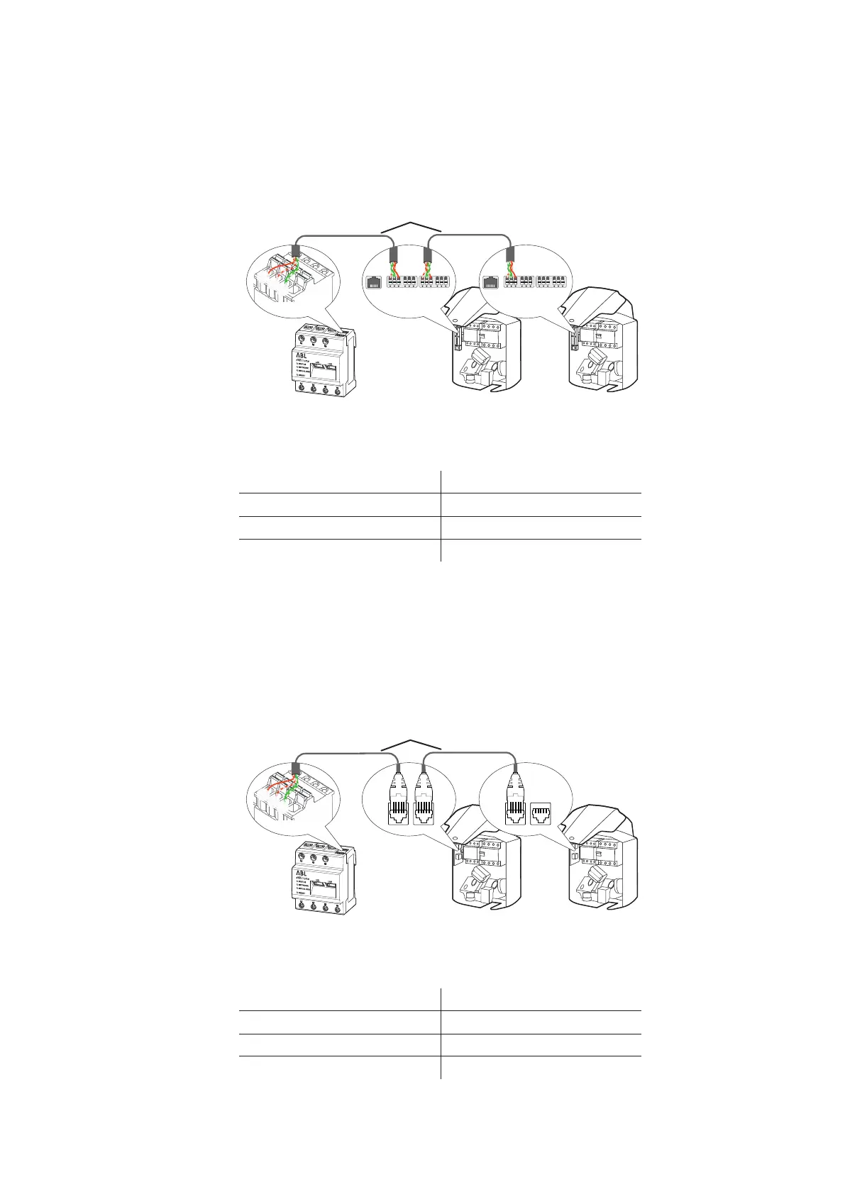
Bus wiring via E2I interface
For bus wiring via the E2I interfaces (for products manufactured from mid-2021), the following generally applies:
The data line is connected to the internal interfaces in the wallboxes via RJ45 connectors.
For pre-assembled cables with RJ45 connectors, the colour assignment within the data lines is already prede-
fined. In this case, the assignment to the RS485 terminal of the eMShome must be adapted in accordance with
the assignment below.
If you would like to assemble the data cables yourself, you should also use the following assignment as a guide
(see also “PIN allocation within the system” onpage49):
RS485 terminal (eMShome) eMH1 E2I interface pins
Pin 3 1
Pin 4 2
Pin 2 3 & 6
eMShome Wallbox 1 Wallbox X
A M B
evcc/rfid
A M B
meter
A M B
evcc/rfid
A M B
meter
A M B
evcc/rfid
A M B
meter
A M B
evcc/rfid
A M B
meter
4
3
2
Data cable
eMShome Wallbox 1 Wallbox X
4
3
2
Data cable
 Loading...