33
LVD SCSIDE Bridge Manual
3.9 Jumper Setting on AEC-7722
JP2 is mainly used to set each device’s ID number on the SCSI adapter. Give your
IDE device a specific number according to the following figure.
1 for ID1
left 2 for ID2
right 3 for ID4
4 for ID8
5 for RSV0
Figure 3-17 6 for RSV1
7 for LED
Figure 3-16
1 2 3 4 5 6 7
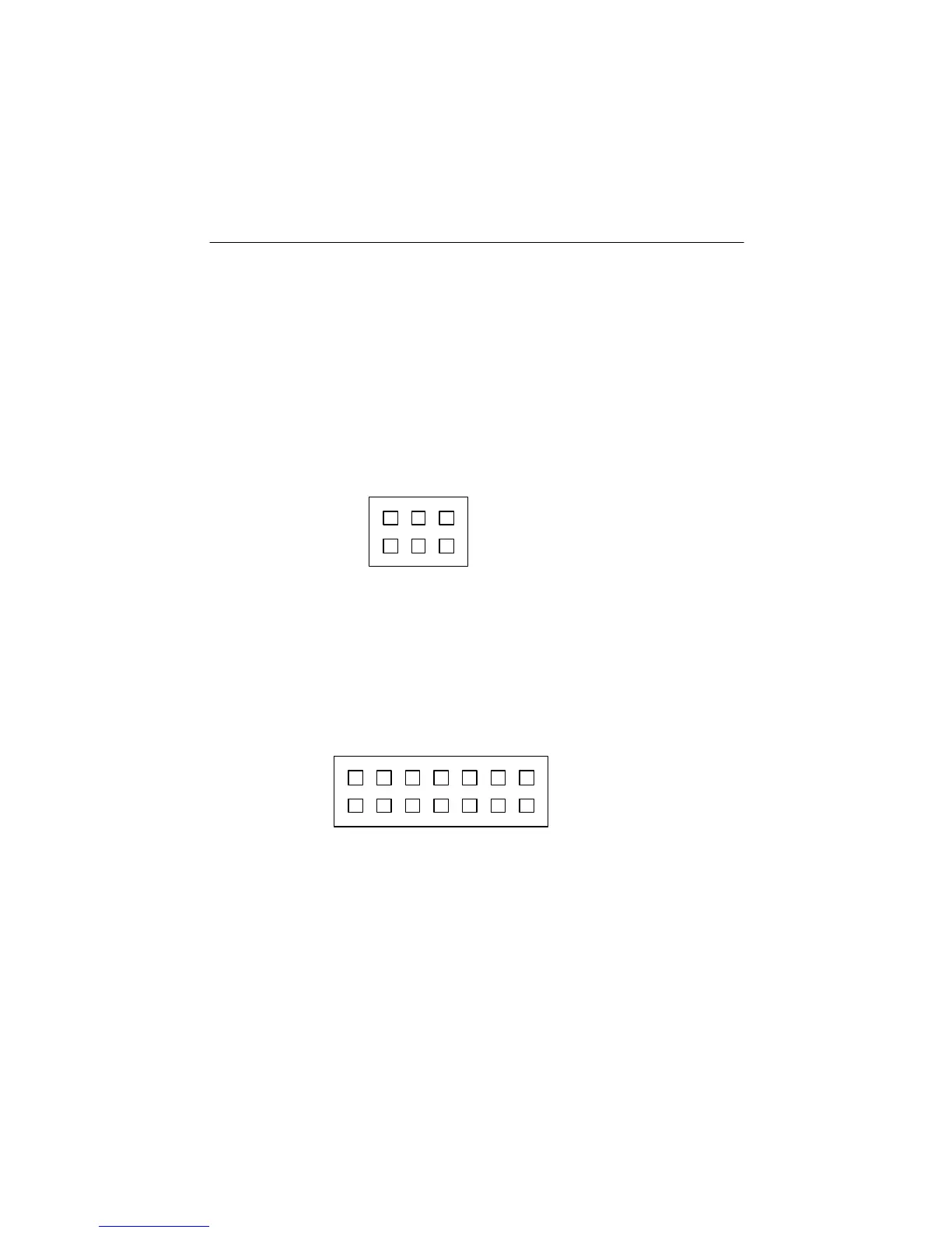
There are two jumpers on AEC-7722: JP1 and JP2. JP1 has 6 pins in 3 columns.
Column 1 and 2 are for reserve, and column 3 is for single end (SE). JP2 has 14 pins
in 7 columns. Column 1 is for ID1, column 2 for ID2, column 3 for ID4, column 4
for ID8, column 5 for reserve 0, column 6 for reserve 1, and column 7 for LED.
JP1 is mainly used to set for single end (SE).
left 1 for reserve
2 for reserve
right 3 for SE
1 2 3