34
LVD SCSIDE Bridge Manual
3.10 Jumper Setting on AEC-7726H/Q
There is only one jumper on AEC-7726H/Q. JP1 has 14 pins in 7 columns. Column
1 is for ID1, column 2 for ID2, column 3 for ID4, column 4 for ID8, column 5 for
RSV0, column 6 for RSV1 and column 7 for LED.
JP1 is mainly used to set each device’s ID number on the SCSI adatper. Give your
IDE device a specific number according to the following figure.
top 1 for ID1
2 for ID2
3 for ID4
4 for ID8
5 for RSV0
6 for RSV1
7 for LED
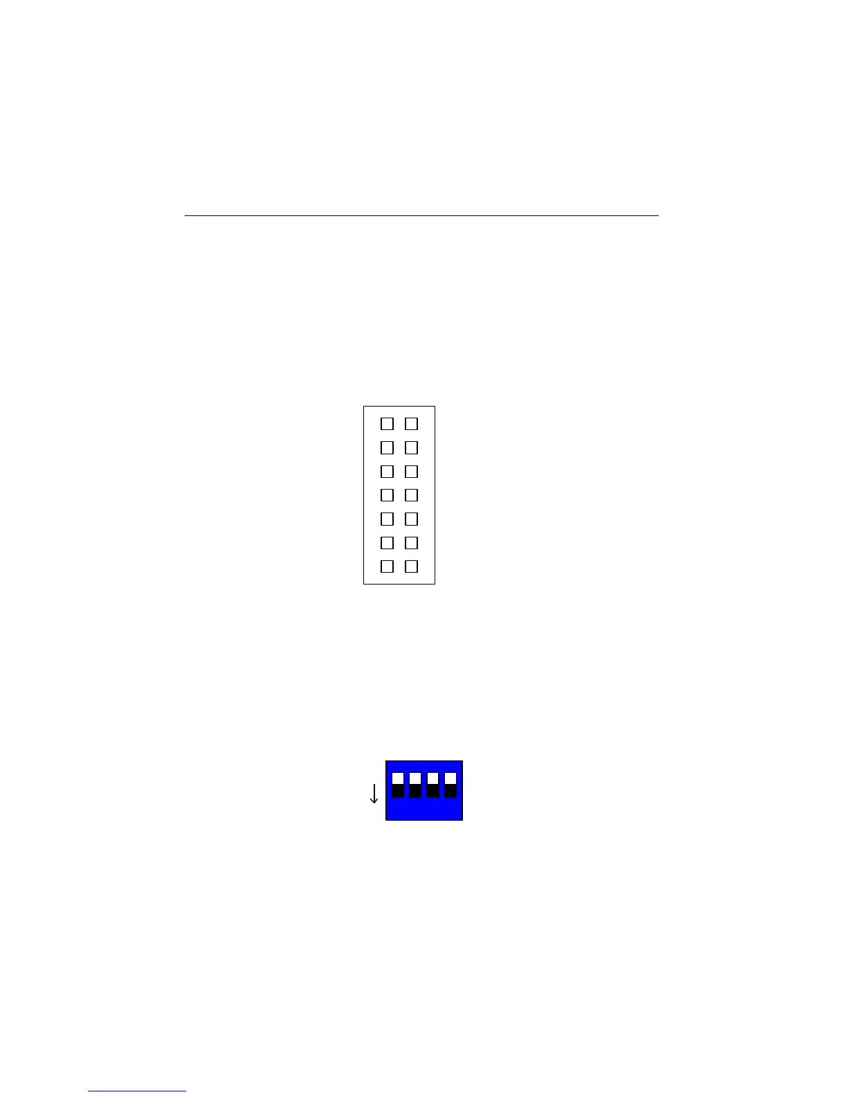
3.11 Jumper Setting on ARS-2100/2100Q
SW1 is mainly used to set each device’s ID number on the SCSI adatper. Give your
IDE device a specific number according to the following figure.
Figure 3-18
1 for ID1
2 for ID2
3 for ID4
4 for ID8
Figure 3-19
1 2 3 4
ON