36
LVD SCSIDE Bridge Manual
3.13 Jumper Setting on ARS-2000LFS
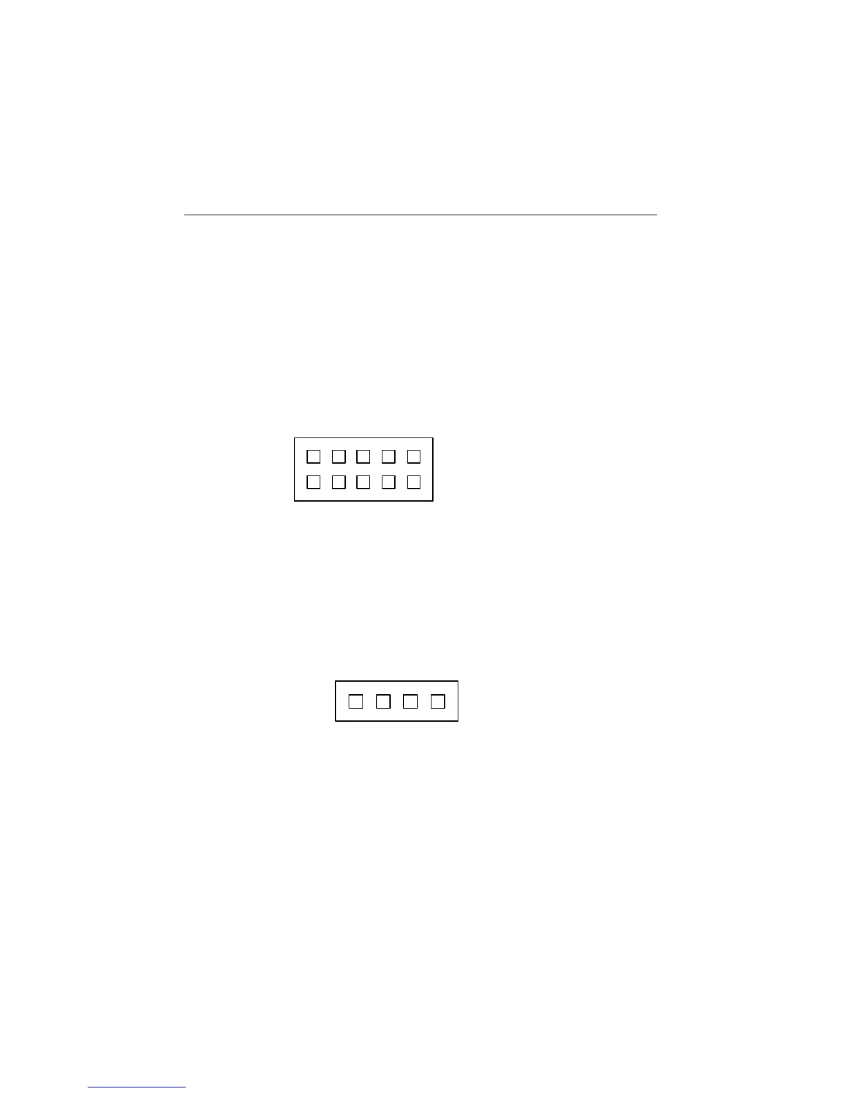
There is one jumper on ARS-2000LFS. JP1 has 10 pins in 5 columns. Column 1 is
for ID1, column 2 for ID2, column 3 for ID4, column 4 for ID8, and column 5 for
delay start (to control the drive’s spin-up).
JP1 is mainly used to set each device’s ID number on the SCSI adatper. Give your
IDE device a specific number according to the following figure.
left 1 for ID1
2 for ID2
right 3 for ID4
4 for ID8
Figure 3-22 5 for delay start
(control the drive’s spin-up)
Besides, there is a SW1 on ARS-2000LFS. Its definition is as the following figure
shows.
1 for Force Single End
2 for RSV0
3 for RSV1
4 for RSV2
Figure 3-23
1 2 3 4 5
1 2 3 4