AccuAir Rocker Switch Manual V2.7 © 2007 AccuAir Control Systems, L.L.C.
- Page 11 -
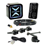
Wiring Harness Installation Considerations
• The plugs that connect to the ECU will only t in the desired orientation. Do
not force the connectors into the wrong mating connector.
• Make sure to press all connectors on rmly until an audible “click” sound can
be heard from the lock.
• Route all wiring away from exhaust or other hi-temp areas.
• Use Rubber Grommets for areas where sharp metal could eventually wear
through the wire insulation.
Step-By-Step
•ECU Main Harness
1.) First connect the Main Harness at the ECU then route each section to each
component on the vehicle.
2.) Route the Rocker Switch sub harness (gray 7-wire bundle) to the inside of the
vehicle and leave until later in installation.
3.) Route the 3-wire Tank Pressure Sensor sub harness (green, red, and black
wires) labeled “P_SENS” to the sensor.
5.) Route the single yellow wire labeled “COMP_1” with a 3 Amp fuse to trigger
the Compressor Relay(s).
6.) Route the single red wire labeled “BATT_12V” with a 10 Amp fuse to the
vehicle battery.
7.) Mount the single black wire labeled “EC_GND” with the VU4 ground.
Install Wiring Harnesses:
See System Diagram
on pages 4-5.
CLICK !