115
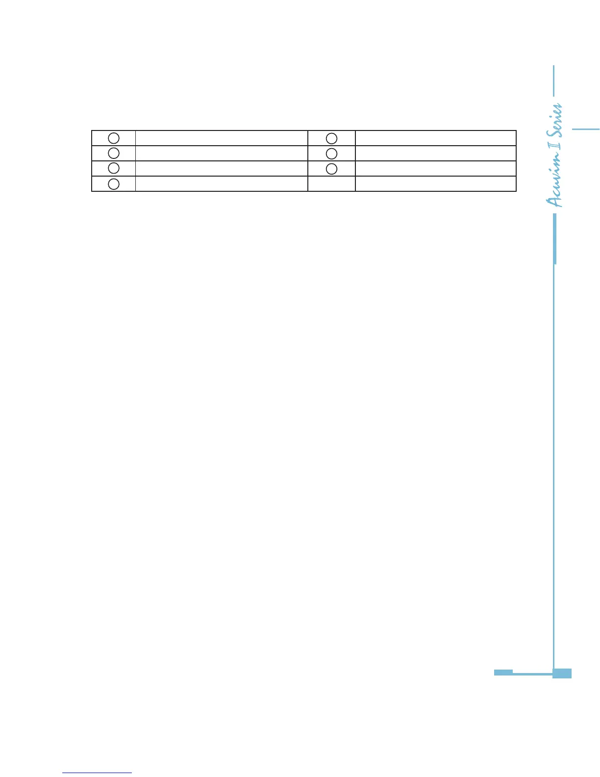
1 Enclosure 5 Installation screw
2 Wiring Terminals 6 Counterpart of clip
3 Linking pins 7 Installation clip
4 Linking socket
5.1.4 Installation Method
Environment
Please verify the installation environment meets the requirements listed as
follows:
Temperature
Operation: -25ºC to 70ºC
Storage: -40ºC to 85ºC
Humidity
5% to 95% non-condensing.
Location
The Acuvim II meter and IO modules should be installed in a dry and dust free
environment avoiding heat, radiation and high electrical noise sources.
Installation Method
With the link pins, IO modules are linked to the meter and to each other. The
maximum number of extended modules linked to Acuvim II meter, including
IO module, Ethernet module Profibus module, RS-485 module and BACnet
module, is three. The communication modules must be installed rst. No other
module can be installed before them.
1. Insert the installation clips to the counterpart of Acuvim II meter, and then
Fig 5-1 Dimensions

 Loading...


