119
There are 6 digital input circuits, 4 digital input circuits and 4 digital input
circuits in AXM-IO1, AXM-IO2 and AXM-IO3 modules respectively. The digital
input circuit can be used to detect remote signals, or be used as an input pulse
counter.
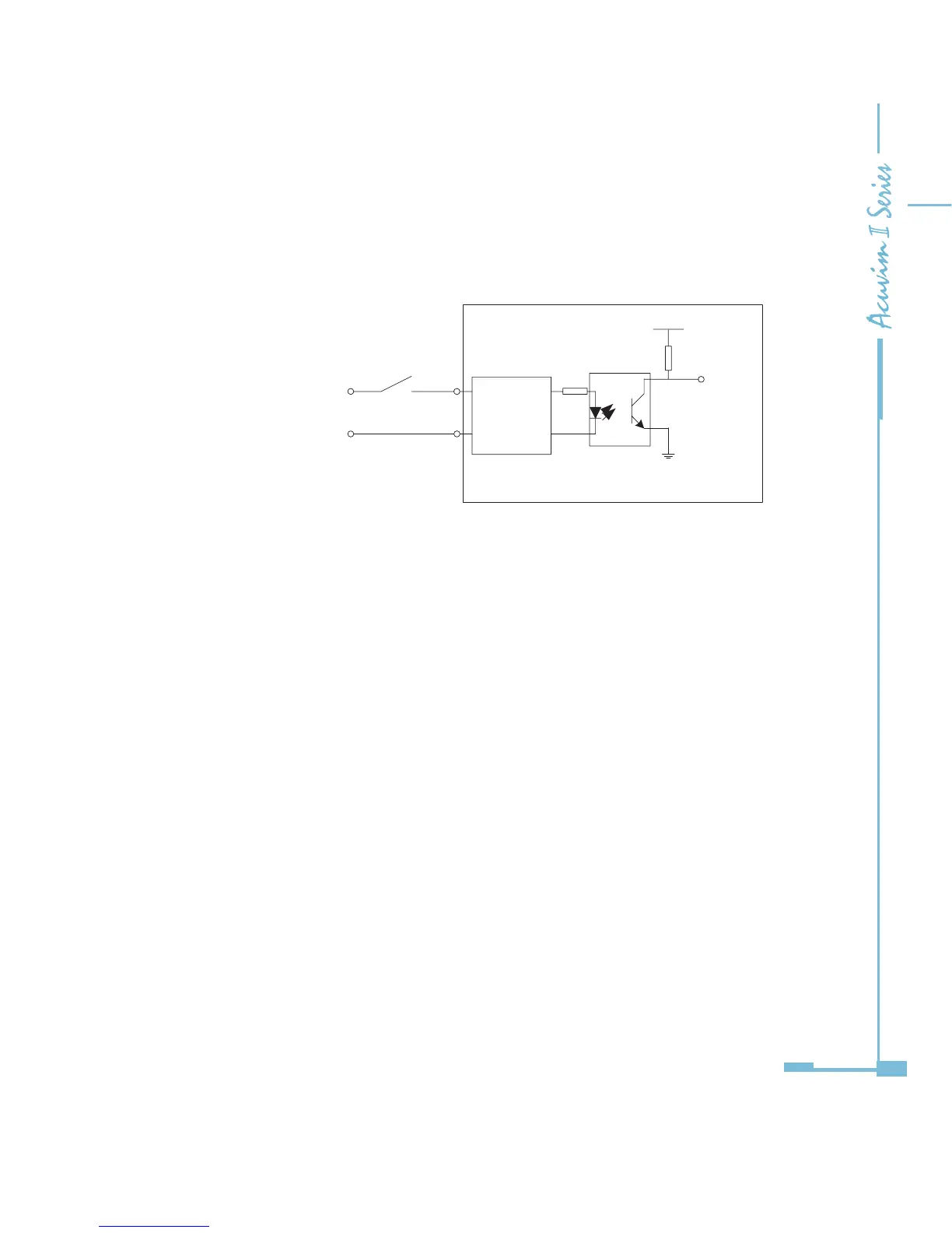
Fig 5-6 schematic diagram of digital input circuit
The circuit drawing of digital input is simplied as shown in Fig 5-6. When K is
switched o, OUT is in high state. When K is switched on, OUT is in low state.
The external power supply for the digital input is 20-160 Vad/Vdc. The max
current in the loop line is 2mA.
The wire of digital input should be chosen between AWG22~16 or 0.5~ 1.3mm
2
.
Wiring of Relay Output Circuit:
There are 2 relay output circuits in AXM-IO1 and AXM-IO3 modules respectively.
The relay output circuit can work in controlling state, or an alarm state. When
it operates in controlling state, it has two optional output modes, latching and
pulse. When it operates in alarm state, it has only one latching output mode.
Relay type is mechanical Form A contact with 3A/250Vac or 3A/30Vdc. A
mediate relay is recommended in the output circuit as in Fig 5-7.
16
Electrical
Adjuster
VCC
R
OUT
20~ 0V AC /DC
K
DIn
DIC
IO module
Optical
coupler

 Loading...


