120
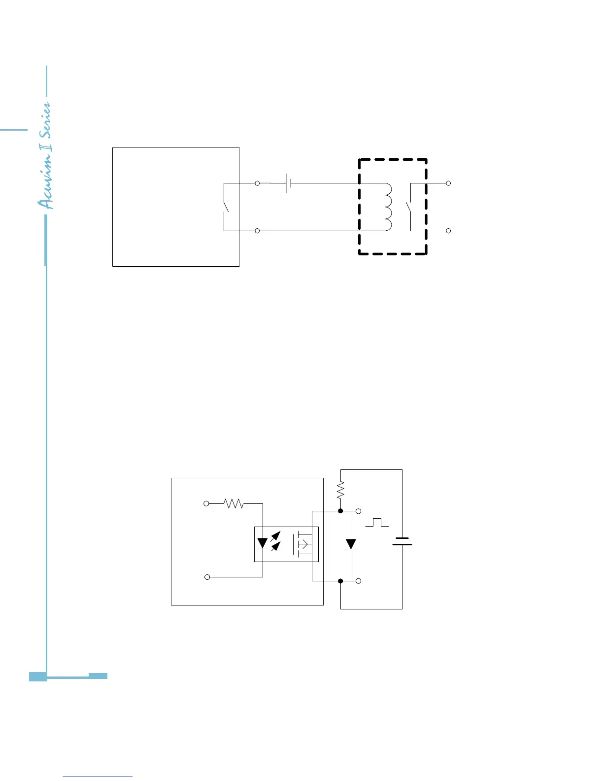
Fig 5-7 schematic diagram of relay output circuit
The wire of relay output should be chosen between AWG22~16 or 0.5~1.3mm
2
.
Wiring of Digital Output Circuit:
There are 2 digital output circuits in AXM-IO2 module. The digital output circuit
can work in alarm state, or work in energy pulse output state.
Digital output circuit form is Photo-MOS. The simplied circuit is shown in Fig
5-8
Fig 5-8 schematic diagram of digital output circuit 1

 Loading...


