195
with the binary contents correctly justied with each byte. For each register, the
first byte contains the high order bits and the second contains the low order
bits.
It is important to note: The response has a 16-word frame. so the maximum
“quantity of registers” should less than 15. Otherwise, it will return an error
result.
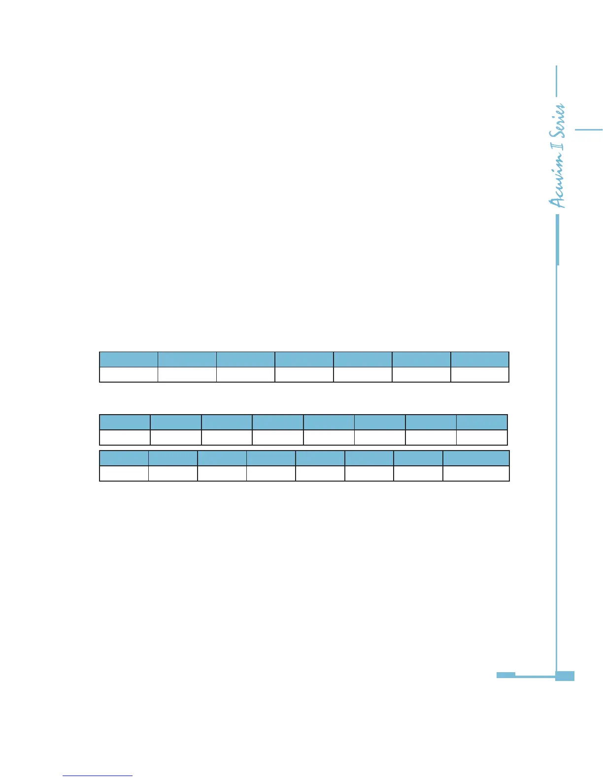
Example: reading 3 measured data (F,V1,V2) from Acuvim II meter. The data
address of F includes 4000H and 4001H. The data address of V1 includes 4002H
and 4003H. The data address of V2 includes 4004H and 4005H. (Use 7 channels)
Table 5-28
Query
Byte1 Byte2 Byte3 Byte4 Byte5 Byte6 Byte7~32
07H 03H 40H 00H 00H 06H 00H
Response
Byte1 Byte2 Byte3 Byte4 Byte5 Byte6 Byte7 Byte8
07H 03H 0CH 42H 48H 00H 00H 42H
Byte9 Byte10 Byte11 Byte12 Byte13 Byte14 Byte15 Byten16~32
C7H CCH CDH 42H C8H 33H 33H 00H
(F=42480000H(50.00Hz), V1=42C7CCCDH(99.9v), V2=42C83333H(100.1v)).
Note: The relationship between the numerical value in the register of the meter
and the actual physical value is described in detail in Chapter 6.
5.3.16 Format of function code 10H
This function code is used in MODBUS-RTU to write a block of continuous
registers in the Acuvim II meter, such as system parameters setting and so on. In
PROFIBUS-DP, the format of function code 10H is dened as follows:

 Loading...


