EasyManua.ls Logo

AccuEnergy Acuvim II series User Manual

AccuEnergy Acuvim II series
350 pages
To Next Page IconTo Next Page
To Previous Page IconTo Previous Page
Page #245 background imageLoading...
Page #245 background image
237
Query
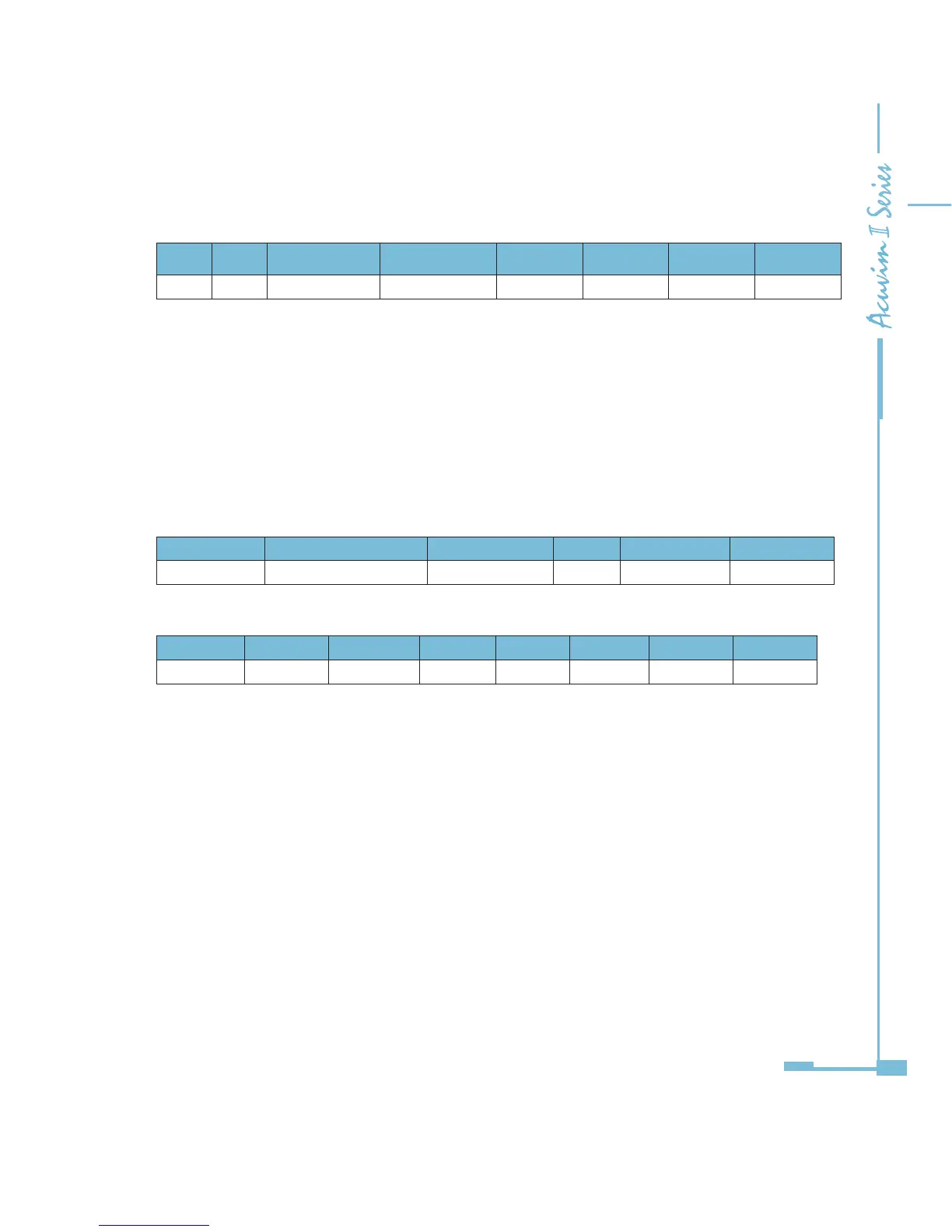
Table 6-6 Read 4 DIs Query Message
Addr Fun DI start addr HI DI start addr LO DI num HI DI num LO CRC 16 HI CRC 16 LO
11H 02H 00H 00H 00H 04H 7BH 59H
Response
The Acuvim II series meter response includes the meter address, function code,
quantity of data characters, the actual data characters and error checking. An
example response to read the status of 4 DIs are shown in Table 5-7. The DI
status corresponds to the last 4 bits of the data.
DI1: bit0; DI2: bit1; DI3: bit2; DI4: bit3.
Table 6-7 Read Status of DI
Address Function code Byte count Data CRC high CRC low
11H 02H 01H 03H E5H 49H
The content of the data is:
7 6 5 4 3 2 1 0
0 0 0 0 0 0 1 1
MSB LSB
DI1=On, DI2=On, DI3=O, DI4=O.
3. Read Data (Function Code 03)
Query
This function allows the master to obtain the measurement results from the
Acuvim II series meter. Table 6-8 is an example of reading the measured data (F,
V1 and V2) from slave device number 17, the data address of F is 4000H, 4001H;
V1's address is 4002H, 4003, and V2's address is 4004H, 4005H.
Question and Answer IconNeed help?

Do you have a question about the AccuEnergy Acuvim II series and is the answer not in the manual?

AccuEnergy Acuvim II series Specifications

General IconGeneral
BrandAccuEnergy
ModelAcuvim II series
CategoryMeasuring Instruments
LanguageEnglish

Summary

Chapter 2 Installation

2.2 Installation Methods

Covers environmental considerations and step-by-step panel cutout and mounting instructions.

2.3 Wiring

Explains terminal strip layout, power requirements, and common wiring diagrams for different systems.

Chapter 3 Meter Display and Parameter Settings

3.7 Parameter Setting Mode

Guides users on accessing and modifying system, I/O, network, and alarm parameters.

Chapter 4 Detailed Functions and Software

4.4 Over/Under Limit Alarming

Guides on setting up and triggering alarms when parameters exceed preset limits.

4.5 Data Logging

Explains configuring historical data logs with parameters, intervals, and sectors.

4.7 Power Quality Event Logging and Waveform Capture

Covers logging events like voltage sags/swells and capturing waveforms.

Chapter 5 Extended Modules

5.2 Ethernet Module (AXM-NET)

Details Modbus-TCP, HTTP, SNTP, and email functions for network communication.

Chapter 6 Communication

6.1 Modbus Protocol Introduction

Explains Modbus RTU protocol, data frame format, and transmission modes.

6.3.1 System Parameter Setting

Explains how system parameters determine meter operation and function codes.

6.3.4 Over/Under Limit Alarming Setting

Covers global and single channel alarm settings.

6.3.5 I/O Modules Settings

Explains how to change I/O module settings based on installed modules.

Related product manuals