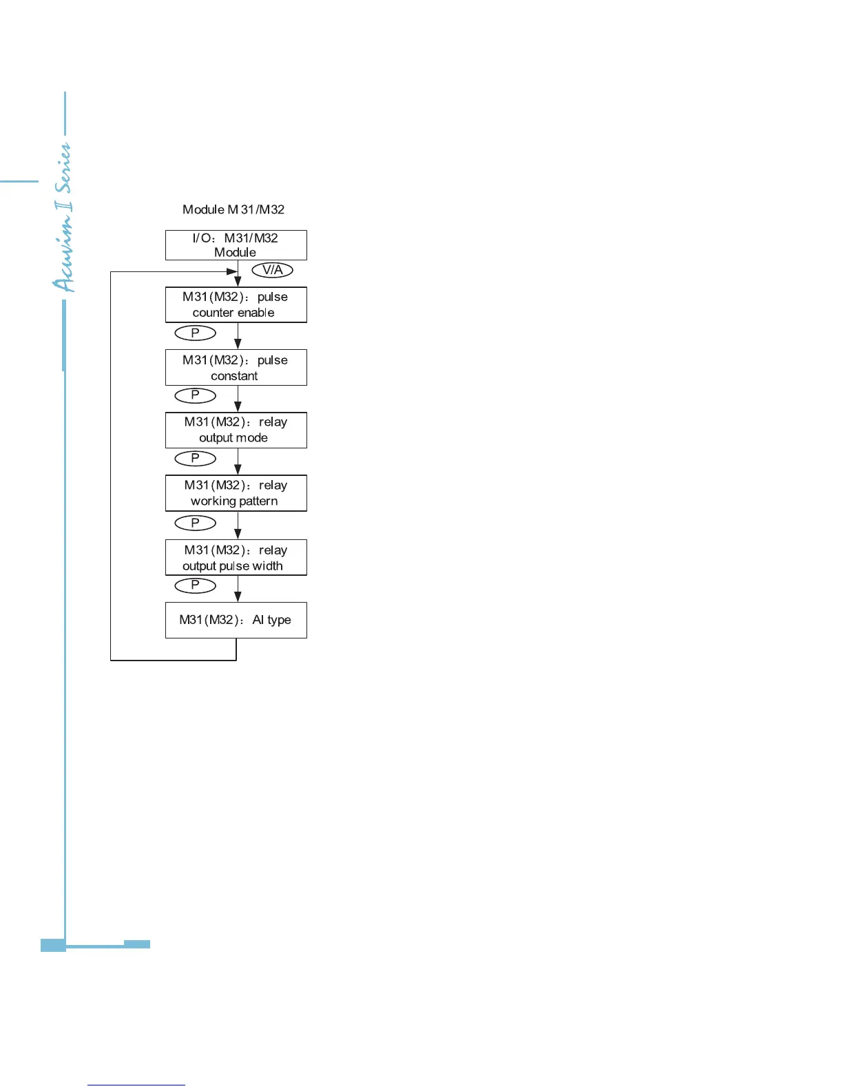
DI of AXM-IO3 can be used as the pulse counter, each DI function
corresponds to one bit of a 4-bit register. The correspondence bit
of 0 means that the DI works as the digital status input and the
correspondence bit of 1 means that the DI works as the pulse counter. For
example, if the setting value is 0001, it means that DI1 is set as the pulse
counter and other DIs work as digital status inputs.
If the DI works as a pulse counter, when the number of pulses counted
by the DI equals to the pulse constant, the pulse counter will increase
by one. This means that the actual pulse number equals the number of
pulses counted multiplied by the pulse constant.
When set as control output, relays have two control methods: latch or
pulse
Relays of AXM-IO3 can be used as alarm output or control output.
ALM:alarm output; CTRL:control output
If relay pulse control method is selected, the relay contact will close for
a preset period and open afterwards. The pulse width range is 50~3000
ms.
Range from 0 to 3. 0: 0~20mA; 1: 4~20mA; 2: 0~5V; 3: 1~5V.
Be aware that modules with current option cannot be set as voltage type
(i.e. option 2 and 3 are unavailable); modules with voltage option cannot
be set as current type (i.e. option 0 and 1 are unavailable).

 Loading...


