MOUNTING AND WIRING 4-19
SB1391 Hardware and Setup Guide - Document revision no. 1.14
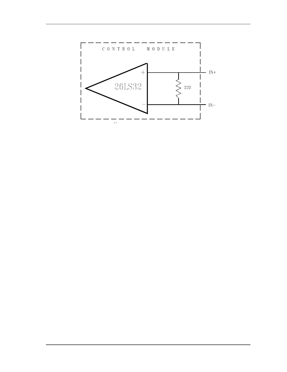
FIGURE 4-16 Encoder interface
Each encoder feedback interface (primary and master) accepts three-channel, differential, TTL
level signals.
The input buffer is built around 26LS32 line receivers.
It is recommended to use encoders with built-in line drivers, AM26LS31 or similar.
4.4.3.2. Sensor Inputs
There are three Hall sensors (in motors that include Hall sensors): A, B, and C. The connection
for each Hall sensor is shown in FIGURE 4-17.
Instead of Hall sensors, some motors are supplied with encoders that have special commutation
tracks. Those tracks can be connected instead of the Hall connection signals.