MOUNTING AND WIRING 4-23
SB1391 Hardware and Setup Guide - Document revision no. 1.14
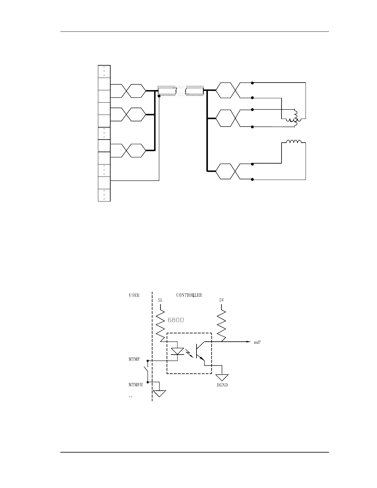
FIGURE 4-20 Resolver connection
4.4.3.5. Motor Temperature
A normally closed switch should be connected between the MTMP pin 15 and the MTMPR pin
11. When the temperature of the motor exceeds the limit, the switch must open (FIGURE 4-21).
FIGURE 4-21 Switch connection for temperature protection
2
3
4
5
9
10
12
Resolver Control
Unit
Cos
CosL
Sin
SinL
Ref
Agnd
Screen
Resolver / Encoder 1
Cos
CosL
Sin
SinL
Ref
Ref
L
Shield
Cos
CosL
Sin
SinL
Ref
Ref
L