4-34 MOUNTING AND WIRING
SB1391 Hardware and Setup Guide - Document revision no. 1.14
During control unit startup, the 7-segment display goes on (i.e., displays an "8") for a few seconds
to show it is functioning properly and then goes off.
For information about programming the 7-segment display, to display system and ACSPL
program messages, refer to Chapter 7, "HARDWARE INTERFACE PARAMETERS."
4.5.3. DIP Switches
Two DIP switches are located on the front panel of the control module. The Prog switch is
reserved and the COM_SD switch disables communication.
When the COM_SD switch is ON, the following limitations apply:
• Control module receives (accepts) only responses to ACSPL input statements and user
defined function keys (FKEY_#).
• Control module transmits only messages generated by ACSPL disp statements.
PROG.
COM_SD
ON
1
2
FIGURE 4-29 DIP switches (off)
TABLE 4-24 DIP switches
Switch ON
PROG.
For future use. Must always be set to ON.
COM_SD
Partial communication shutdown.
Note
For CAN communication, the COM_SD switch must be OFF.
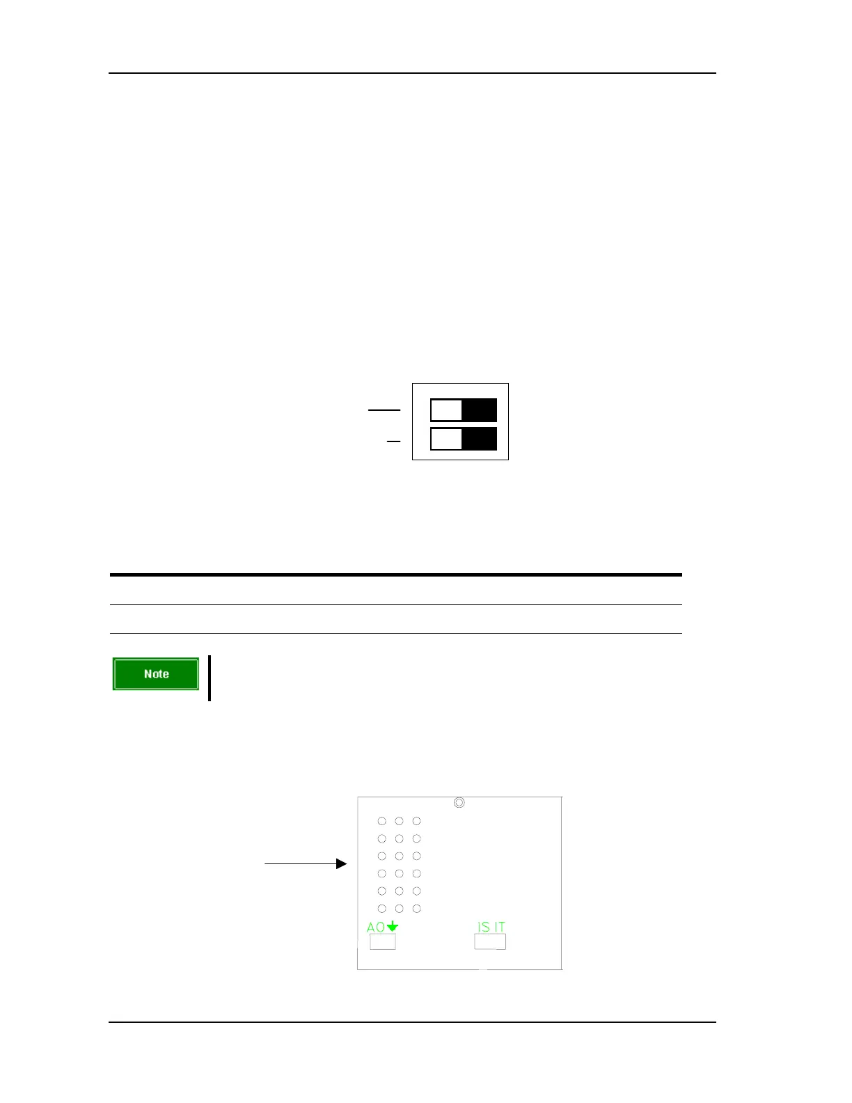
4.5.4. Test Points
The test points are located on the bottom of the control module.
Front panel
FIGURE 4-30 Location of current test points