20
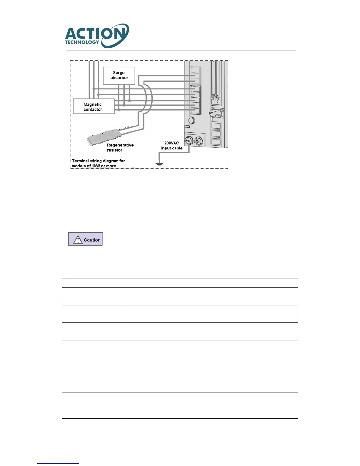
[Points for correct wiring]
※ 24VDC and 200VAC input (main circuit) power supply should be wired from the same 200VAC main power supply.
※ Do not access switch between 24VDC power supply and drive. If you need switch, put it on the 200VAC cable of 24VDC
input power supply.
※ A twisted-pair shielded cable should be used when I/O cable length is over 50cm.
※ The encoder cable should be less than 20m.
① Please note that there is high voltage in the solid line of wiring diagram when wiring and using.
② The broken lines in the wiring diagram indicates the non-dangerous voltage circuit.
3.1.2 Connection of servo drive and motor
Conform to European EC Directive. Select the device which meets corresponding standards
and install them in accordance with User’s Manual.
Install the servo drive to the environment which conform to Pollution degree 2 or 1 of
IEC60664-1.
Power supply 1: 200~
230VAC (main circuit)
This product can be used under the conditions that conform to IEC60664-1 and overvoltage
category Ⅱ.
Power supply 2: 24VDC
♦ control power supply of drive
♦ I/O power supply
♦ Power supply for brake
release
The specification of 24VDC external power supply should satisfy the following conditions.
Using SELV power supply(※) and power less than 150W. This is the CE corresponding
conditions.
※SELV: safety extra low voltage
(Reinforced insulation is needed for safety extra low voltage, non-dangerous voltage and
dangerous voltage.)
Please use withstand voltage cables which are equivalent to AWG18/600V or AWG14/600V
for motor power cable, encoder cable, AC220 input cable, FG cable and main circuit power
distribution cable under multi-axis drive structure respectively when drives are less than