First Power up
Before power up for Optima compact only - fit
the top cover on to the base and connect the
speaker wires. Leave the cover in position
throughout the reset of the installation.
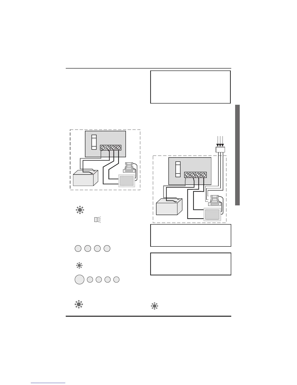
a.
Check that the factory fitted links are
connected to terminals PA, TAMP and
T-A.
b. Fit the battery wires to the BATT
terminals on the PCB, Red to + and
Black to -.
c. On connecting the battery the system
will now go into alarm condition and
Tamper is indicated
and there is an audible
indication. .
d. Fit the cover to hold down the tamper
spring at the bottom centre of the PCB.
e.
Enter the user code:
(factory set at
0123). The alarm condition will cease
and the system will go to Day mode
.
f. Immediately enter the engineer code
.
The system is now in Engineer
program mode and can be
programmed. Note the
Tamper indicator is lit.
Note: The G3 range of panels are not
supplied with wire links for unused
zones. All unused zones must be
programmed out by setting them to
disabled using the Zone Type function
see page 19.
Mains Connection
The mains power should be connected using a
3 core cable of not less than 0.75mm sq. from a
fused spur to the mains connector inside the
control panel. The 2 Amp fused spur must be
located close to the control panel.
Note: The mains supply must be
connected by a technically competent
person and according to current IEE
regulations.
CAUTION: To avoid the risk of
electrical shock you must always totally
isolate the mains supply before opening
the control panel cover(s).
ÿ
Mains Input Fuse rating: 125mA, 250V type
T (anti surge) and of a type approved to IEC
127 part 2 sheet III.
On connecting the mains supply to the panel the
power indicator is lit.
4PI175 issue 1_6/01 11
Accenta/Optima G3 intruder system Engineering information
First Power up
N
L
E
Transformer
125mA Fuse
Panel
+-
AC
1.6A
BATTERY
BATT
J4
F1
Board
(red)
+
Black -
12V battery
Tampe