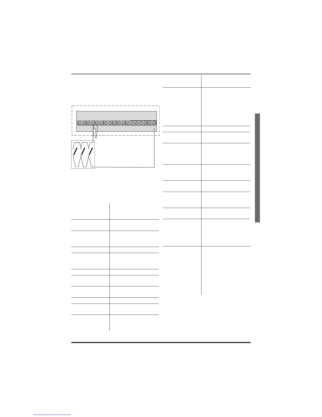
j. Where Pressure mats are being used
these must be connected to a zone in
the manner shown. The example below
shows pressure mats connected to
zones 3.
Specification
Indicators on
Control panel or
RKPs
Zone 1-8, Power, Attack,
Tamper and Day
8 Zones
+ve loop, programmable
function in each program
Tamper
-ve loop, internal
sounders in Day – Full
alarm in Set
PA +ve loop, always active
Bell Output
12V, adjustable timer
(1-99 mins) or
continuous
Strobe Output 12V latching
Extension Speaker
16 ohms (2 maximum)
130mA each
Exit/Entry timers
seconds
Programmable (10-990
seconds)
Zone Input Delay 300 or 800mS
Set +ve Output
0V in Day (sinking
40mA)
Current
Consumption
Control panel
Standby 80mA
Alarm 250mA
Current
consumption RKP
Standby 40mA
Alarm 70mA
Low voltage
output
13.8V dc stabilised (+/-
5%) up to 350mA
Rechargeable
Battery
Accenta/Optima G3
mini/compact - 12V, 1.2
or 2.1Ah
Accenta/Optima G3
- 12V, up to 7Ah
Charge Voltage 13.8V dc (+/-5%)
PCB Fuses
1.6A & 1A 20mm quick
blow
Mains Input fuse
125mA, 250V type T
(anti-surge) type
approved to IEC 127,
part 2 sheet III
Total Current
Output
1Amp when supported
by a fully charged
battery
Mains Supply
Voltage
230V (+/-10%) 50Hz
max load 0.2A
Total Current
Output
1Amp when supported
by a fully charged
battery
Mains Supply
Voltage
230V (+/-10%) 50Hz
max load 0.2A
Ambient
Operating
temperature
0 –40degC
Enclosure
construction
3mm Polycarbonate
Dimensions
Accenta/Optima G3
mini/compact
H 200mm W 253mm
D 55mm
Accenta/Optima G3
H 230mm W 290mm
D 80mm
RKP H 85mm W
122mm D 28mm
4PI175 issue 1_6/01 25
Accenta/Optima G3 intruder system Engineering information
Specification
J2
2
1
4
3
6
5
8
7
Panel
PA
+
-
TAMP
+13V 0V
Board
Pressure Mats
33Kohms