Features
ÿ
8 zones, all programmable for Security,
Fire, 24H Fire, PTS or keyswitch
applications
ÿ
PA input
ÿ
Tamper input
ÿ
Outputs for Bell and Strobe
ÿ
4 Access level Codes, User 1, User 2,
Engineer and Duress, all programmable
ÿ
3 fully selectable part set programs
ÿ
Chime on any zone
ÿ
8 event memory
ÿ
Programmable timers including bell cut off
ÿ
Walk Test facilities
ÿ Quick set feature
ÿ
Remote keypad with on board PA and
illuminated keys standard for Accenta
panels and Optional for Optima panels
ÿ
Option for connection of Lighting
controllers
ÿ
Options to connect up to four remote
keypads / Lighting controllers
ÿ
NVM for protection of engineer programme
ÿ
6 digital outputs for a wire-in digital
communicator, Red Care STU or dialler
(Not applicable for Optima compact G3
panel)
ÿ
Service warning indicator, programmable
between 100 and 800 set and unset events
ÿ
Battery capacity of up to :
2.1Ah in Accenta/Optima G3 mini enclosure
7Ah in Accenta/Optima G3 enclosure
ÿ
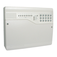
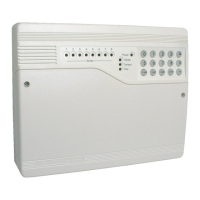
Optima G3 and Optima G3 mini are supplied
with built in keypad
2 4PI175 issue 1_6/01
Engineering information Accenta/Optima G3 Intruder system
Features
Contents
Features -------------------2
Installation Design --------------3
Fixing --------------------3
Wiring the system --------------5
Tamper network ---------------5
Connect Remote Keypads / Lighting controllers 5
Security zones ----------------5
Push to set zone ---------------6
Remote keyswitch zone -----------6
Fire zone ------------------6
PA circuit ------------------6
Extension speaker --------------7
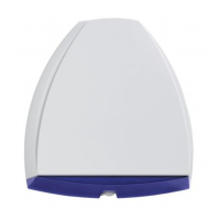
Bell Output (External sounder) --------7
13V Supply output --------------8
Set ---------------------8
Remote signalling Input and Outputs -----8
Filtering of Intruder alarms -----------9
Factory set condition -------------10
First Power up ----------------11
Mains Connection --------------11
Testing the system --------------12
Engineer program mode -----------12
To exit ---------------------12
System indications --------------12
To enter Engineer program mode -------12
To Exit Engineer program mode -------12
To reset panel to Factory set conditions ----12
Access Codes ----------------13
Programs ------------------14
Zone Function per Program----------14
Exit Modes program -------------14
Programs 1,2 and 3--------------15
Alarm and Walk tests ------------16
Communicator tests -------------17
‘Flag A’ Options ---------------17
‘Flag B’ options ---------------18
Viewing the event log ------------18
Zone Type ------------------19
Zone Attributes ---------------20
Bell and Service Timers -----------21
Re-arm and Anticode reset code -------22
Lighting controller --------------23
Faults --------------------24
Specification-----------------25
Servicing organisation Details --------27
Parts --------------------27
Quick Reference ---------------28
8
z
RKP
4
PART
SET
MEM
8
OUTPUT
6
REMOTE
SET
5
0
9