A are then used for tamper protection for the
sounder housing.
Where self contained / powered sounders are
used, carefully follow the manufacturers
instructions, match each of the terminals to
those above.
13V Supply output
The 13V output is to power detectors which
require a voltage supply (PIR detectors etc). The
supply is present at all times and may be used to
supply a total load of 350mA.
Set
The output , marked SET is used with latching
detectors. The output becomes positive on
correct Set of the system and is removed at the
commencement of entry time or entry of the
valid user code.
Remote signalling Input and
Outputs
These outputs are not applicable to the
Optima compact G3 panel.
These terminals have been provided for
connection to remote signalling equipment such
as a digital communicator, Red Care STU or
speech dialler.
Note: The operating polarity of the
Communicator output terminals are
programmable.
L/FAIL This is a telephone line fail input which
is held at approximately 6V by the panel
circuitry. The input is activated when pulled to
0V by the telephone line fault output of the
communicator. This is usually a voltage free
relay or open collector transistor.
When a telephone line fault occurs in the Day
mode the panel provides an audible double beep
every 10 minutes. This indication is
automatically cleared when the fault is removed.
A telephone line fault which occurs while the
system is Set will not cause an alarm condition
but any bell delay which is programmed will be
cancelled and any intruder alarm which is
triggered will operate instant sounders.
13V 0V These terminals provide a 13V supply
for the communicator up to a total load of
200mA. The output is protected by a 250mA
thermal fuse. If this fuse operates it may be reset
by removing the load and allowing a few
seconds for it to recover.
OUTPUT PORT By default these outputs are
programmed as active low output. They are held
at 13V and fall to 0V when active, it can source
or sink 10mA. The output polarity can be
programmed.
8 4PI175 issue 1_6/01
Engineering information Accenta/Optima G3 Intruder system
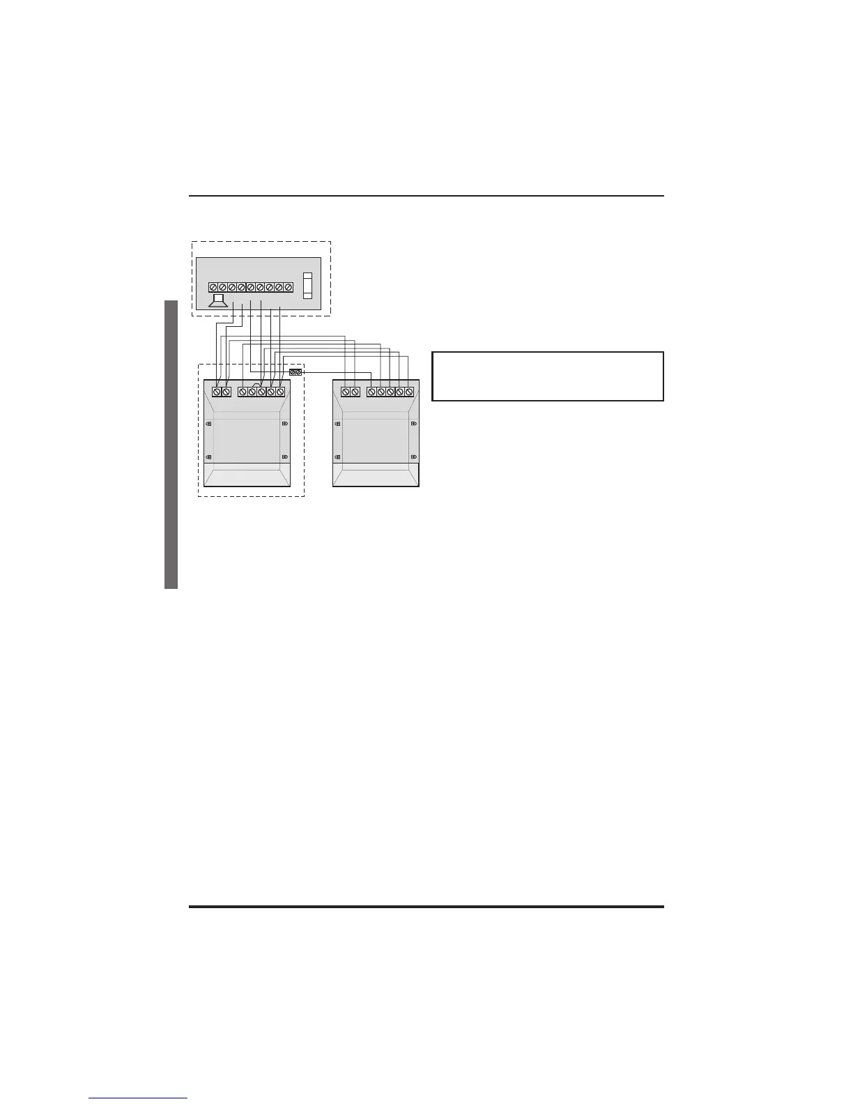
13V Supply output
# Terminal block
is not supplied
-
STROBE
J6
+
TA
SCB
DB
BELL
+
-
SET
1A
BELL/STROBE
F5
Sonade
Panel
Board
+- TEADB
STROBE
#
Sonade
+- TEADB
STROBE