NetVanta 3000 Series Hardware Installation Guide OVERVIEW
61200860L1-34L Copyright © 2006 ADTRAN, Inc. 29
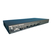
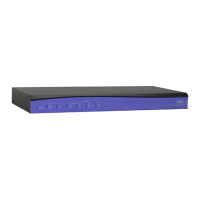
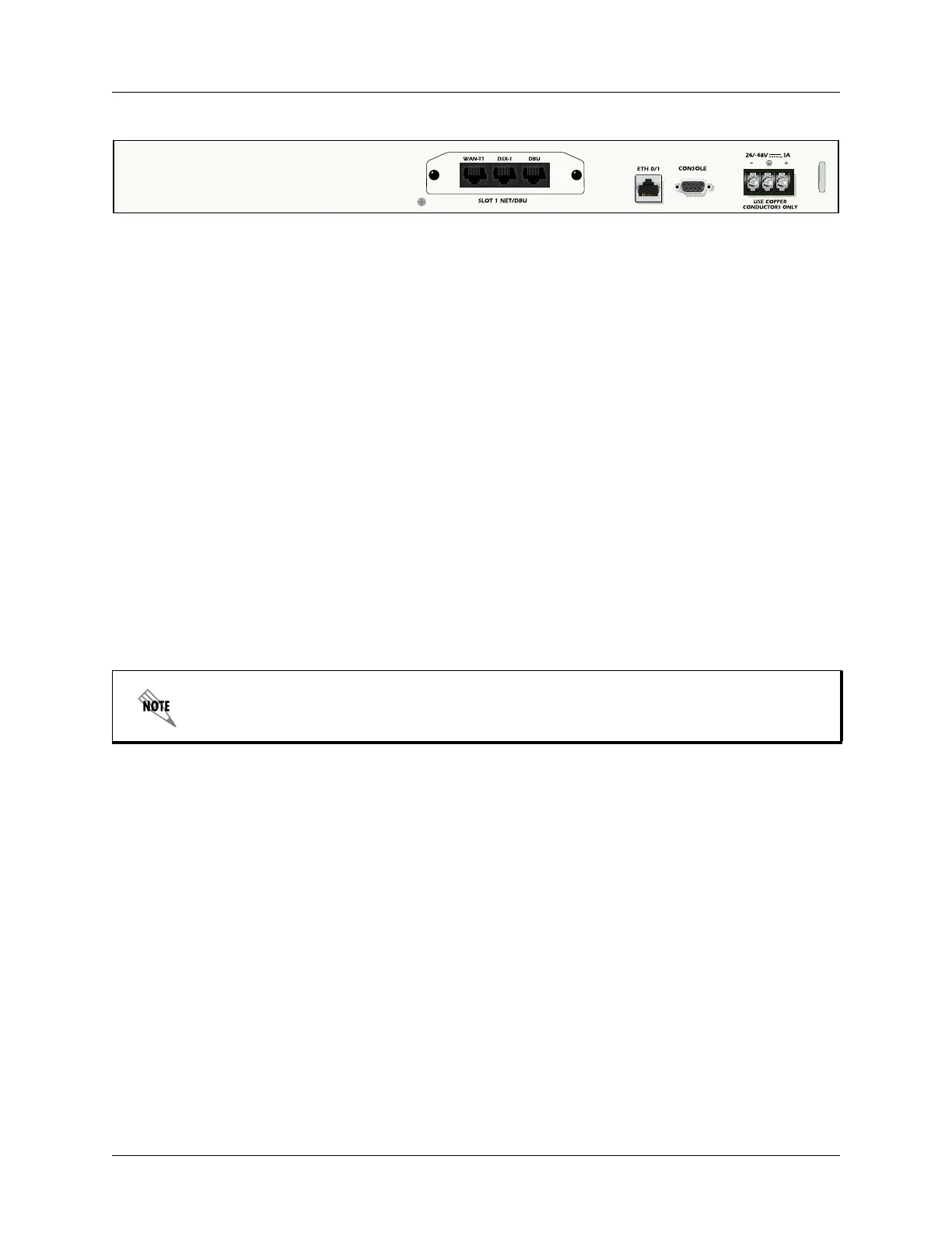
Figure 9. NetVanta 3205 (DC version) Rear Panel Layout
NetVanta 3205 Rear Panel Interfaces and LEDs
SLOT 1 NET/DBU Option Slot
The SLOT 1 NET/DBU option slot supports various NIM plug-in option modules. These option
modules are described in the section Option Modules on page 43.
10/100BaseT Ethernet Interface and Activity LEDs
The Ethernet port (ETH 0/1) is an RJ-45 connector with LEDs. The amber activity LED flashes when
data traffic is being sent or received on the Ethernet port. The green link LED is on when the router has
a good connection to the LAN. The Ethernet port provides the following:
• 10BaseT or 100BaseT with a single connector
• Auto-negotiation
•CSMA/CD
• IEEE 802.3 compatibility
CONSOLE Interface
The CONSOLE interface is an EIA-232 serial port (DCE) which provides for local management and
configuration (via a DB-9 female connector).
Power Connection
The rear panel has a power input for connection to the power supply. Power supplies are shipped with
final destinations in mind. For example, domestic routers are shipped with a wallmount supply and
international routers are shipped with a universal input lump-in-line supply with the appropriate
cables. All of the 1U-high products have universal power supplies and are shipped with the appropriate
cable. Please refer to Supplying Power to the Unit on page 66 for connection details.
Connection directly to an external modem requires a cross-over cable.
 Loading...