UNO-2271G_V2 User Manual 12
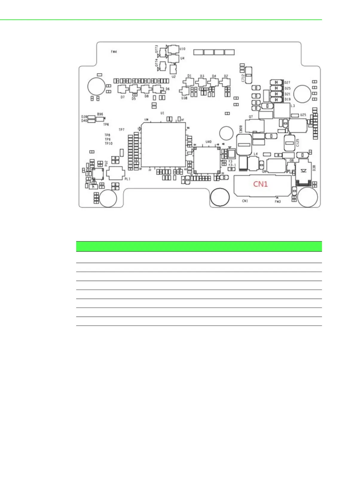
Figure 2.8 Locations Internal I/O Connectors/Switches for UNO-2271G-RP1EA
(Bottom Side) (Optional)
2.1.3.1 M.2 B-key Connector
There is one M.2 B Key connector for M.2 cards, labeled “CN2” on the expansion
board. This M.2 interface is a SATA signal co-lay with a USB3.0 signal. It will auto-
matically detect which device you installed and determine the appropriate SATA or
USB signal to use. Therefore, it supports the installation of M.2 2242 (w/SATA signal)
or 3042/3052 module (w/ USB Signal).
(Please refer to user manual-chapter 3.3 & 3.5 for installation details and User Man-
ual-Appendix A.6 for pin assignments.)
2.1.3.2 M.2 E-key Connector
There is one M.2 E Key connector for M.2 cards, labeled “CN40” on the expansion
board. This M.2 interface is a PCIe signal and USB2.0 signal. it supports the installa-
tion of M.2 2230 WiFi module.
2.1.3.3 mPCIe Connector
There’s one sockets for full size PCI Express mini cards, labeled “CN3” on the board.
Table 2.2: Internal Connectors and Jumper Switches
Label Function
CN4 COM Port Terminal Connector (RS232/422/485)
CN37 LAN Signal Connector
CN2 M.2 B key for 2242/3042/3052 Connector
CN40 M.2 E key for 2230 Connector
CN3 SIM card slot
SW8/SW1 COM port setting switch
CN1 Internal board to board Connector