EN
1205. 6755517_02
35
29. LIST OF CONTROLS FOR THE GUIDED PROCEDURE
Some parameters in the moducontrol board must
be set appropriately on the basis of the type of
system in which the unit is installed.
These modifications, performed by the installer, are
summarised and organised in the following guided
procedures, with which to correctly set the unit
circuit board parameters.
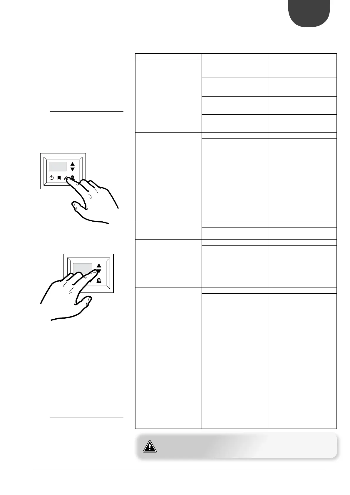
29.1. HOW TO MODIFY A PARAMETER IN
To enter the USER presses shown in , once
you press the key you must enter your password to
access the various menus;
to change the value of the password using the ar-
row keys . Once the correct password, press
shown in
The display reads the USER parameter index and a
three-character string that identifies it, the string is
displayed for a second, after which it is replaced by
the value for the parameter.
To go to the next, use the arrow keys . To
change a parameter, select it by pressing the button
shown in , change the value assigned by the
arrow keys and to confirm the change, press
the switch in .
29.2. HOW TO MODIFY A PARAMETER IN
To enter and edit the menu INSTALLED following
the same procedure for the user menu.
REQUEST ANSWER SOLUTIONS
Is the unit a cooling only model
Radiant panels Set the parameter StC
35 °C
Fan coils or low temperature
radiators
Set the parameter StC
Set the parameter StC
55 °C
Not installed
installed
Set the parameter
PAN
INSTALLER
with the appro-
Season control piloted from the
circuit board
ON/OFF control enabled from PR3
Season control enabled from PR3
ON/OFF control from panel on
machine
Season control enabled from PR3
ON/OFF control enabled from PR3
Not envisioned
envisioned Set the parameter ASA-
-
Not installed
installed Set the parameter AAS
parameter indicates the stand-by
time for inversion of the 3-way
diverter valve on the DHW produc-
tion system
Not envisioned No operation
envisioned This parameter enables a digital
clamp ID
board with the code TRA
which a room thermostat must
be connected, used to disable the
compressors and the integrative
resistances. Set the parameter trA
D INSTALLER
appropriate value, selecting from:
1.
2.
3.
the compressors and resi-
stances block function if the
parameter is set at 1
the compressors, pumps and
resistances block function if the
parameter is set at 2
represents the pump alarm
at the value 3
ATTENTION
For more information, refer to USER manual supplied with the chiller and is also available on
www.aermec.com