Heat
recovery
unit
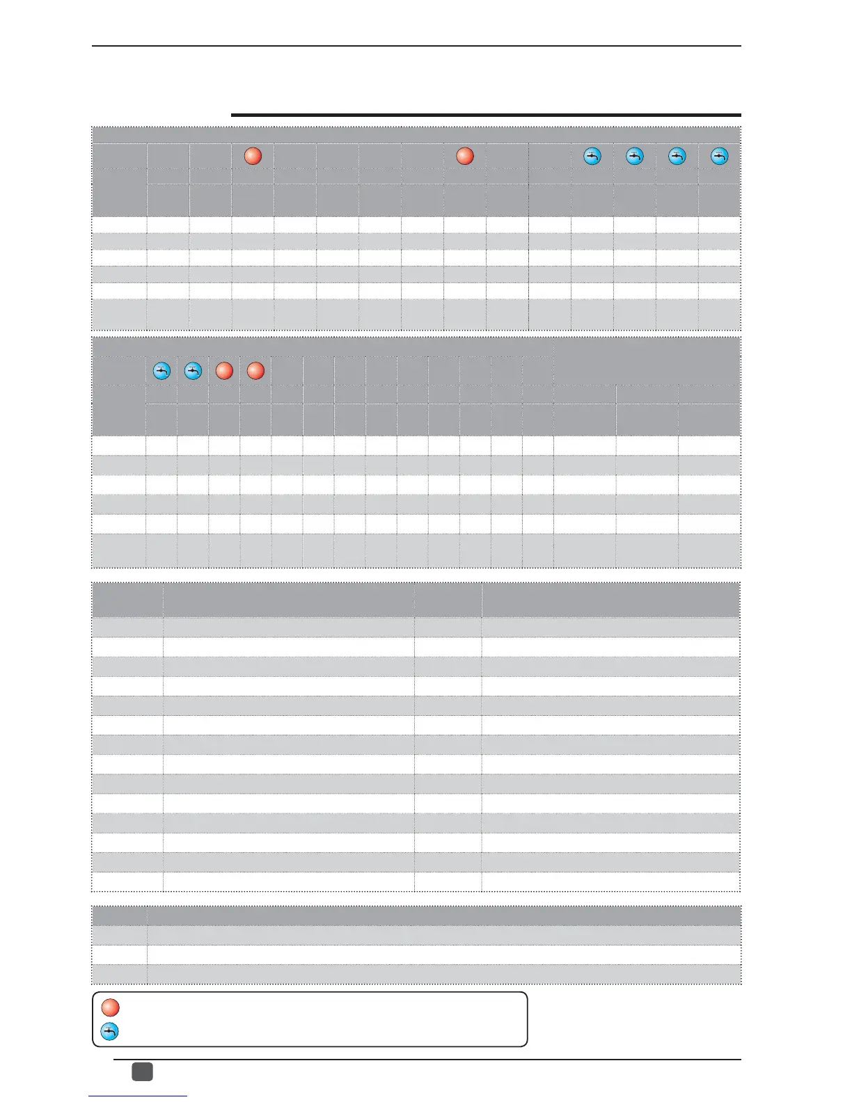
bAF tbF
OAE
Ati SCr Ad1 Bd1 AS1 LA1 St1 LA2 St2 LSP - - -
EFGH I J LNOPQRT 0 1 2
ANL 0 180 45 65 1 1 1 0 -15 43 -10 58 50 6 0 0
ANLI 0 180 45 65 1 1 1 0 -15 43 -10 58 55 6 0 0
ANR 0 180 45 65 1 1 1 0 -15 43 -10 58 55 6 0 0
ANF 0 180 45 65 1 1 1 0 -15 43 -10 58 55 6 0 0
ANK 0 180 45 65 1 1 1 0 -20 53 -10 62 60 6 0 0
SRPV1
SRA
0 180 45 58 0 1 1 0 -20 62 -10 65 63 6 0 0
Contents
index
Meaning of parameter
Contents
index
Meaning of parameter
0 - iu Regulation Input/Output E - bAF Flow switch bypass enabled
1 - oFF Cooling force-off F - tbF Time for flow switch bypass
2 - oFC Heating force-off G - OAE Outside temperature standby
3 - SAF Reset band of force-off H - Ati High temperature of return water
4 - int Integral time I - SCr Screensaver configuration
5 - dEr Derivative time J - Ad1 Modbus supervisor address
6 - AG Anti-freeze L - Bd1 Supervisor baud rate
7 - FrP Frost protection N - AS1 Supervisor write enabled
8 - rin Supplementary electric heater O - LA1 Air temperature limit 1
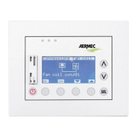
9 - PAN Remote panel configuration P - St1 Water temperature limit 1
A - ASA Enabling domestic water Q - LA2 Air temperature limit 2
B - ASP Power for producing domestic water R - St2 Water temperature limit 2
C - AAS Input standby time T - LSP Maximum heating set point
D - trA Enabling the room thermostat
Alarm Meaning of parameter (INSTALLER menu 2)
0 Delta temperature for reactivating the compressor after FORCE OFF intervention
1 Heating cable configuration
2 Heating cable set point
j