46
GB
6343841_00 / Ver - 4.20
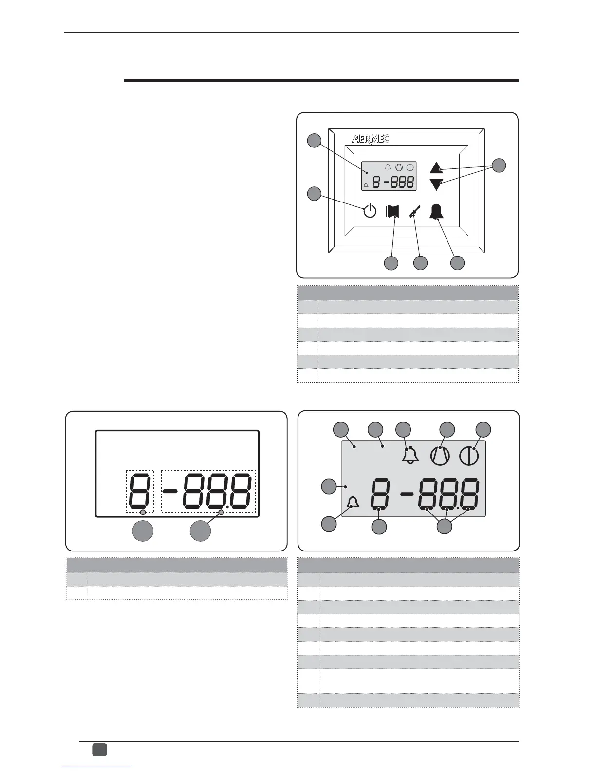
User interface (Fig.1)
A Monitor visualisation
B "ON" key
C Key to access readings menu
D Button key to access set menu
E Button key to access alarm record
F Keys to scroll/increase-decrease parameters
R
SET
dj
A
B
C
D
E
F
User interface and parameter visualisations
Monitor visualisation (Fig.2)
1 SETTINGS menu currently visualised
2 ALARMS menu currently visualised
3 Parameter index
4 Parameter abbreviation / Parameter value
5 Season indicator SUMMER
6 Season indicator WINTER
7 Indicator of current alarm status
8 Indicator of current compressor operational mode (this
indication can have different flashing frequencies).
9 Indicator of stop in progress
A B
The main user interface is represented by a LED panel with
capacitive keyboard (touch keys); the visualisations are ar-
ranged in three menus:
• READINGS menu (key (C) Fig.1)
Containing the information (visualisation mode only) relating
to current unit functioning.
• SETTINGS menu (key (D) Fig.1)
Containing all the parameters that the user can modify accor-
ding to system requirements; these parameters are grouped
together in various sub-menus:
- USER menu (Password 000);
- INSTALLER menu (Password 030);
- ELECTRIC HEATER menu (Password 001);
• ALARM log (key (E) Fig.1)
The alarm log records unit error and/or malfunctioning condi-
tions (whether alarms or pre-alarms).
During normal functioning, the monitor visualises the last pa-
rameter modifi ed; if no other keys are pressed for at least 5
minutes, the monitor activates the screensaver mode (this
function can be set via the parameter (i) in the INSTALLER
menu).
To display parameters and/or readings, 4 fi gures are used;
the fi rst is the indicator i.e. a number allowing the user to
know which parameter or reading he is visualising (Fig.3).
SET
dj
5
6 7
8
9
4
1
2
3
Fig.1
Fig.2
Fig.3
User interface (Fig.3)
A Parameter index
B Parameter abbreviation / Parameter value