Do you have a question about the AERMEC VMF-E5 and is the answer not in the manual?
Proper procedures for disposing of electric, electronic, and battery components.
Interpretation of visual safety alerts like voltage hazard and danger of moving parts.
Guidelines for maintaining manual integrity and ensuring thorough reading for safe operation.
This manual supports VMF system installation, focusing on installer best practices and system integrity.
Describes the management of 5 distinct zones and their control methods for VMF systems.
Details management of heat pumps, domestic hot water, and heat recovery units within the VMF system.
Components required for implementing Zone A in the VMF system.
Components required for implementing Zone B in the VMF system.
Components required for implementing Zone C in the VMF system.
Components required for implementing Zone D in the VMF system.
Components required for implementing Zone E in the VMF system.
Illustrates the hydraulic flow and connections between VMF system components and zones.
Identifies key components to be installed in the technical room for the VMF system.
Step-by-step procedure for installing various components in the technical room.
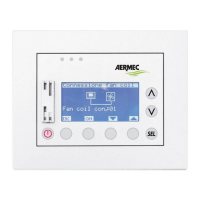
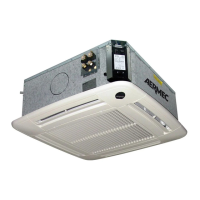
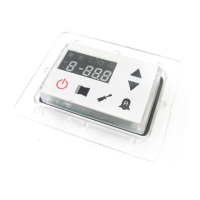
Details material and installation steps for Zone A, including fan coil and control interface.
Details material and installation steps for Zone B, including fan coil and control interface.
Details material and installation steps for Zone C, including fan coil and control interface.
Details material and installation steps for Zone D, including fan coil units and control interface.
Details material and installation steps for Zone E, including fan coil units and control interface.
Diagram illustrating the air-conditioning system's indoor units and their zone assignments.
Details RS485 serial connections between MASTER units and control interfaces.
Explains TTL serial connections for communication between MASTER and SLAVE units.
Describes RS485 connections for system-wide communication with centralized elements.
Guide to accessing and navigating the installer assistance menu, including password entry and basic operations.
Setting master fan coil count, enabling/disabling auto changeover, and performing self-addressing procedures.
Methods for checking fan coil addresses and visualizing overall system communication status.
Configuring VMF-ACS presence, simultaneous loads, and domestic hot water production parameters.
Adjusting Economy mode parameters, heating/cooling temperatures, and chiller board types for optimal performance.
Managing heat recovery units, associating pumps to fan coils, and setting the total number of pumps.
Setting the address and baud rate for the second serial RS485 line for external supervision systems.
| Brand | AERMEC |
|---|---|
| Model | VMF-E5 |
| Category | Control Unit |
| Language | English |