47
GB
6795773_01
If a heat recovery unit is installed in the system, piloted by the
relative VMF-CRP expansion board, it will be possible to set
the logic with which this component is managed;
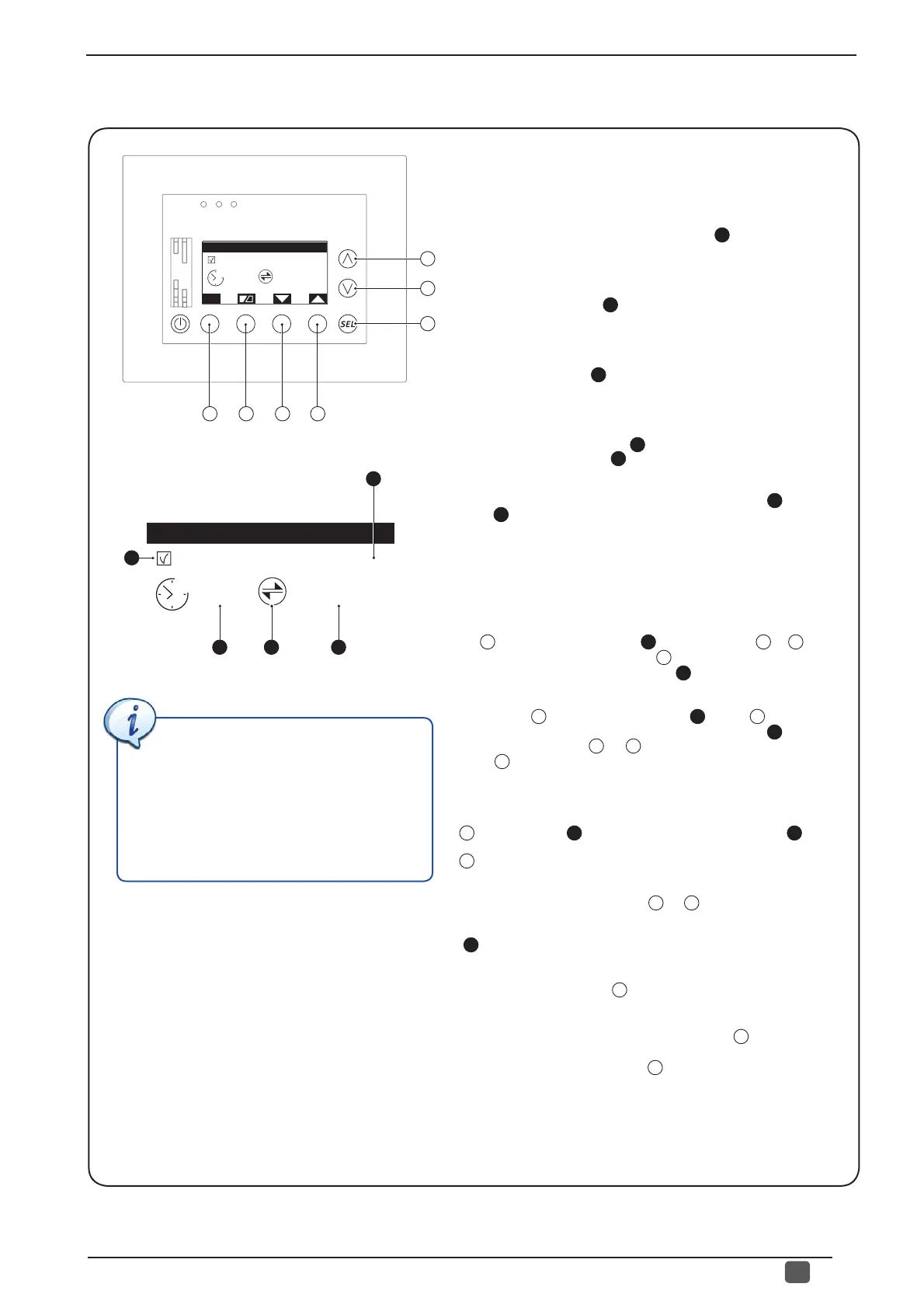
this window
displays the following information:
- Presence of accessory VMF-VOC (
1
): automatically
indicates whether an accessory VMF-VOC probe (to establish
air quality) has been connected to the additional VMF-CRP
module for recovery unit management.
- Recovery unit index (
2
): indicates which recovery unit the
data and settings currently displayed refer to; the VMF-CRP
module of the boiler and recovery units can manage up to 3
different recovery units.
- Hourly program (
3
): indicates which hourly program
to associate to the recovery unit operation (for further
information on hourly programs, refer to the VMF-E5 panel
user manual);
- Air quality value (VOC) (
4
): if selected, it indicates that
the value in percentage
(
5
) represents the value currently read
by the VOC probe installed on the system
.
- Air quality limit for recovery unit activation (
5
): if the
icon
(
4
) is not selected, it indicates the threshold beyond which
to activate the recovery unit; this threshold is only used if a VMF-
VOC probe is installed in the system (keep in mind that the best
air quality corresponds to 0%, while if the value increases it means
that carbon dioxide is increasing).
From this window it is possible to:
(1) Associate an hourly program to the recovery unit: pressing
the
C
key will select the fi eld
(
3
); by pressing the
A
or
B
key,
the value can be changed; press
C
to confi rm the set value,
moving the selection to parameter
(
5
).
(2) Set the activation threshold of the recovery unit with VOC:
pressing the
C
key will select the fi eld
(
3
), press
C
to confi rm
the set value, moving the selection to parameter
(
5
); at this
point by pressing the
A
or
B
key the value can be modifi ed;
press
C
to confi rm the set value, bringing the window to the
visualization status (no value selected).
(3) View the reading of the VMF-VOC probe:
to view the value
currently read by the VMF-VOC probe (if installed), press the
F
key,
the icon
(
4
) will be highlighted and the value (
5
) will
represent the current value read by the VOC probe; pressing the
F
key again will return the window to the normal display.
(4) Select a recovery unit:
if several recovery units are installed
in the system, by pressing
the
E
or
D
key it will be possible
to pass from one recovery unit to another; the recovery unit
which the displayed data refers to is indicated by the label
(
2
).
(5) Pass on to the next window: to go to the next window of
this menu, press the key
B
.
(6) Go back to the previous window: to go back to the
previous window of this menu, press the key
A
.
(7) Exit this window:
press the
G
key to return to the selection
of the menus.
• Set the management mode of the installed heat recovery units
In the proposed example, the system
has a heat recovery unit managed by a
VMF-VOC probe; this recovery unit is not
linked to any time period (therefore the
relative fi eld is at 0), while the recovery
unit should be activated if the room air
deteriorates, and the value read by the
VOC probe exceeds 10%.
A
B
C
G
Program of U.R.C.
ESC
0
Pr
10%
VOC Sen. URC:1
F E D
Program of U.R.C.
0
Pr
10%
VOC Sen. URC:1
1
2
3 4 5