30
GB
6795773_01
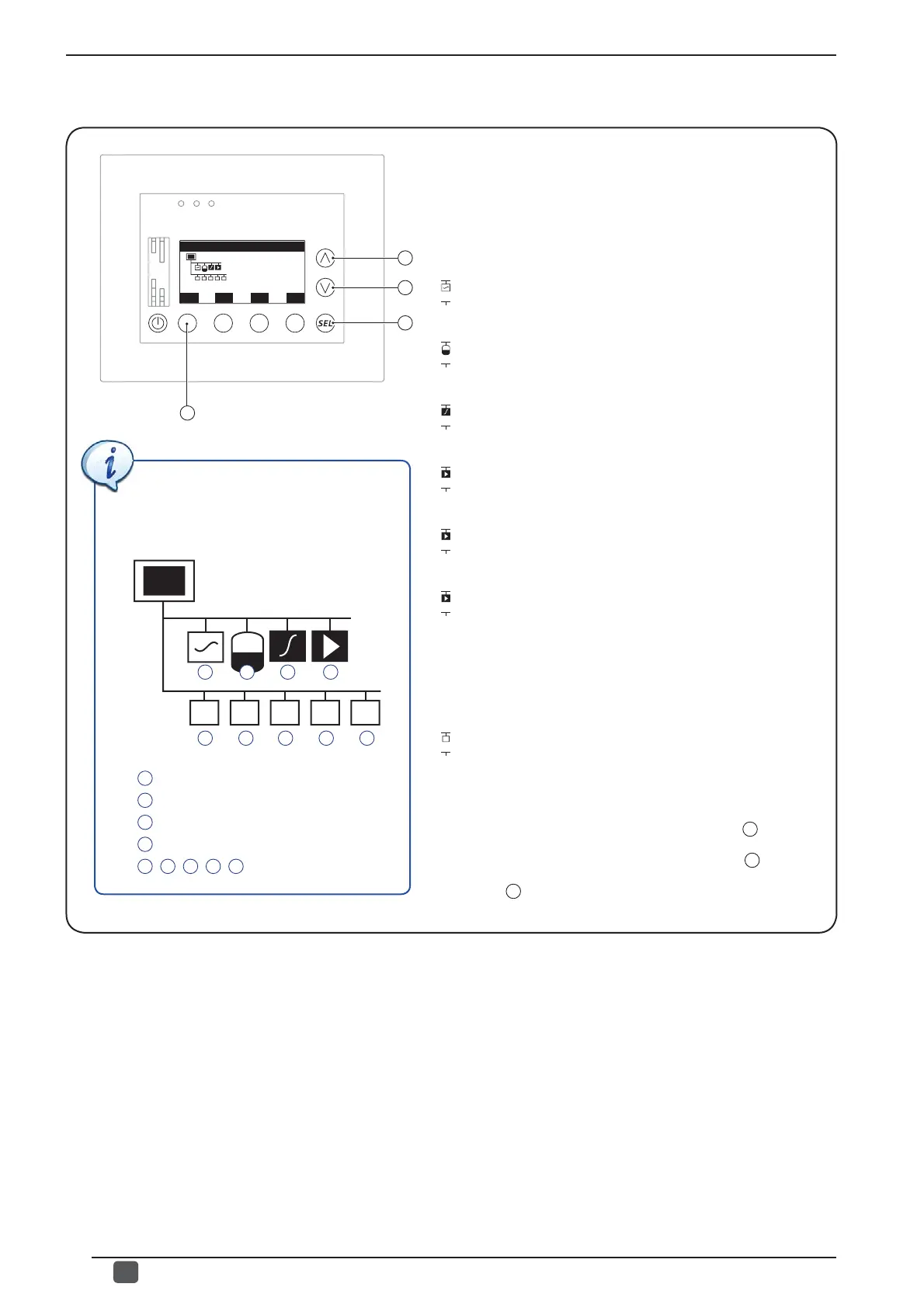
This window indicates the graphic resulting from all parts
connected to the VMF system; the diagram is created dynamically
and represents the status of the serial communications between
the VMF-E5 accessory and the other parts of the system; the
symbols displayed in the graphic are arranged in several rows;
the fi rst can include (from left to right):
• CHILLER:
(
)= Communication with chiller OK;
(
)= Communication with chiller absent.
• DHW accessory:
(
)= Communication with DHW OK;
(
)= Communication with DHW absent.
• VMF-CRP (1) accessory (recovery unit boiler module):
(
)= Communication with VMF-CRP (1) OK;
(
)= Communication with VMF-CRP (1) absent.
• VMF-CRP (2) accessory (pumps 1 module):
(
)= Communication with VMF-CRP (2) OK;
(
)= Communication with VMF-CRP (2) absent.
• VMF-CRP (3) accessory (pumps 2 module):
(
)= Communication with VMF-CRP (3) OK;
(
)= Communication with VMF-CRP (3) absent.
• VMF-CRP (4) accessory (pumps 3 module):
(
)= Communication with VMF-CRP (4) OK;
(
)= Communication with VMF-CRP (4) absent.
The lower rows represent the MASTER fan coils connected
to the VMF network. For these as well the system has an
appropriate symbol describing the status of the serial
communication:
- MASTER fan coil:
(
)= Communication with MASTER fan coil OK;
(
)= Communication with MASTER fan coil absent.
After the status of the network has been controlled, it will be
possible to:
- Pass on to the following window by pressing the
B
key.
- Go back to the previous window by pressing the
A
key.
- Press the
D
key to return to the selection of the menus.
• Visualization of systems status
In the proposed system example, the
system graphic viewed in this window will
refl ect all the settings considered up to
now, and the result will be:
A B C D
E F G H I
A
Chiller;
B
VMF-ACS;
C
VMF-CRP (1) (Boiler and recovery units);
D
VMF-CRP (2) (Pumps);
E
,
F
,
G
,
H
,
I
MASTER fan coil.
A
B
C
Network of plant
ESC
D