9
GB
6795773_01
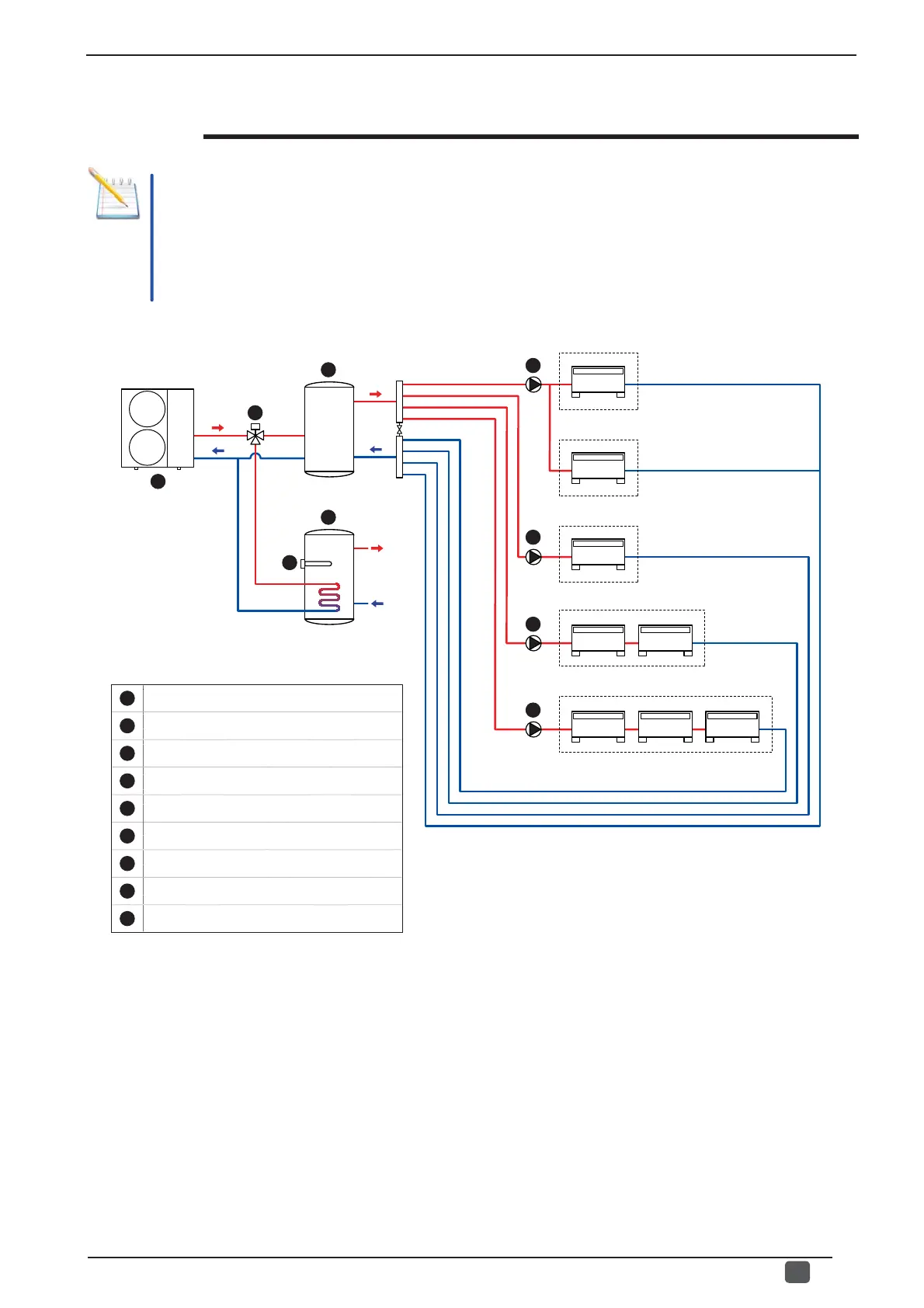
Hydraulic diagram of VMF system
NOTE: VMF systems fully manage an air conditioning/heating system and relative domestic hot water production;
however before implementing a control system, the loads which will be connected to it must be highlighted.
ATTENTION: the installation of the components to implement the system are not taken into consideration
in this manual; for further information concerning installation of the individual hydraulic components, refer
to the component's specifi c documentation.
1
2
3
4
5
6
7
8
9
Zone A
Zone B
Zone C
Zone D
Zone E
1
ANLI.
2
3-way DIVERTER valve.
3
SYSTEM storage tank.
4
DHW storage tank.
5
Supplementary electric resistance (for DHW).
6
Pump for zones A and B.
7
Pump for zone C.
8
Pump for zone D.
9
Pump for zone E.