23
GB
6795773_01
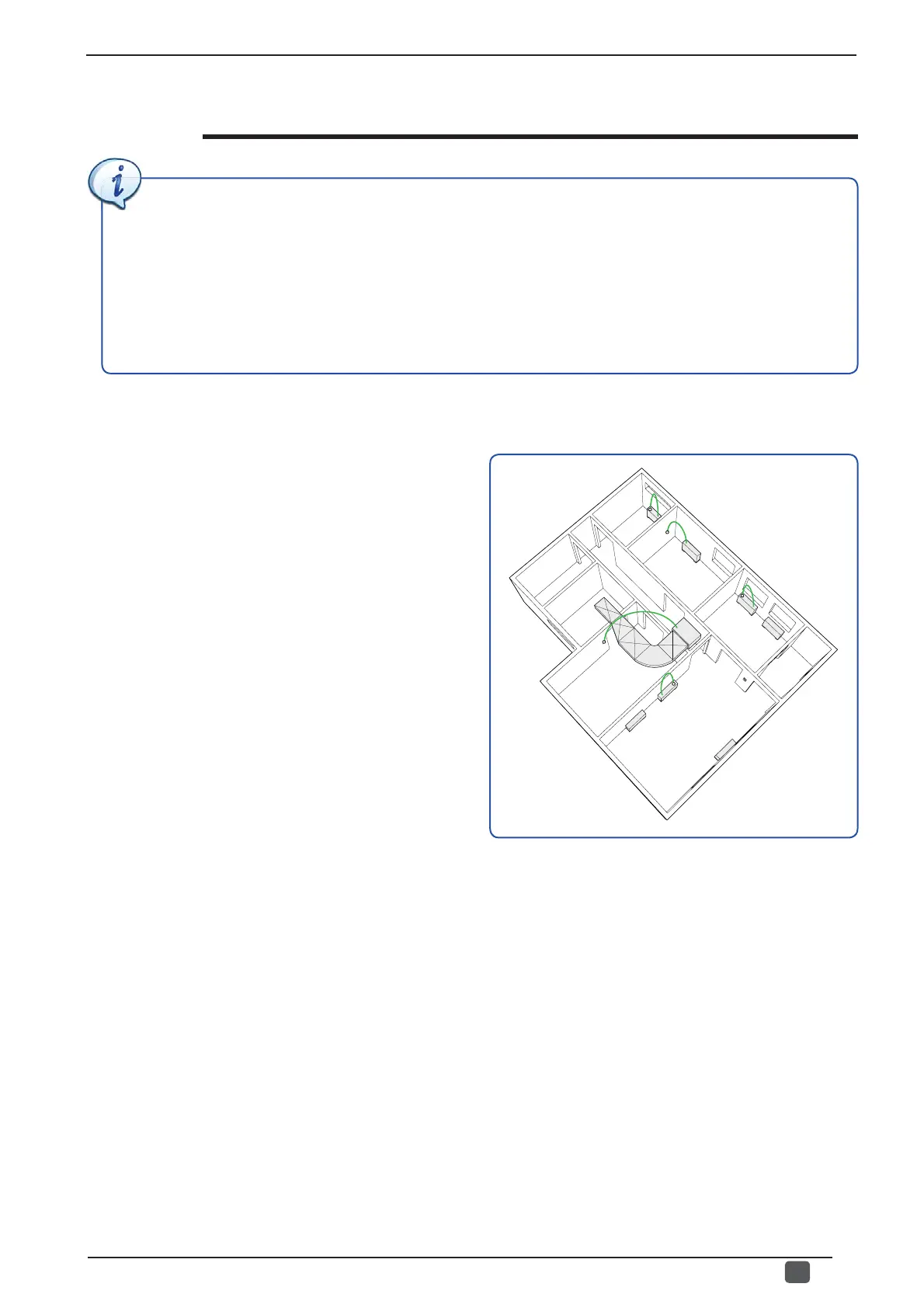
VMF networks serial connections
VMF systems allow managing different air conditioning plant elements with just one control panel; this centralisation
is provided by MODBUS serial communication which, depending on the various components of the system, can
be characterised in the following types:
(1) Serial connections via MASTER and relative control interface;
(2) TTL connections between MASTER and SLAVE;
(3) Main RS485 connection for communication between system and centralised control elements.
The features of each of these categories are:
This type of connection is made between the thermostat of a
Master unit and the relative control device. The thermostats
used as Master can be:
• VMF-E0 (only if a supervision system with VMF-E5 is not
foreseen);
• VMF-E1;
• VMF-E18 (only for inverter units);
• VMF-FCL (only for FCL units).
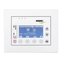
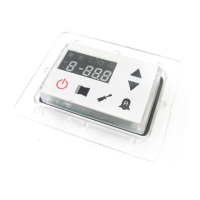
The control devices that can be linked to these thermostats
can be:
• VMF-E2;
• VMF-E2H;
• VMF-E4.
The electric connection of the user interfaces (VMF-E4) to
the master thermostats must be implemented with cables
having the following features:
• Shielded cable for twisted-pair transmission,
AWG 22 - 24 (0.33 - 0.20mm
2
- 4 poles);
• Maximum length of the connection 30m.
For detailed information on the connection between
the thermostat board and control interface, refer to the
specifi c documentation of the accessories.
(1) Serial connections via MASTER and relative control interface