49
GB
6795773_01
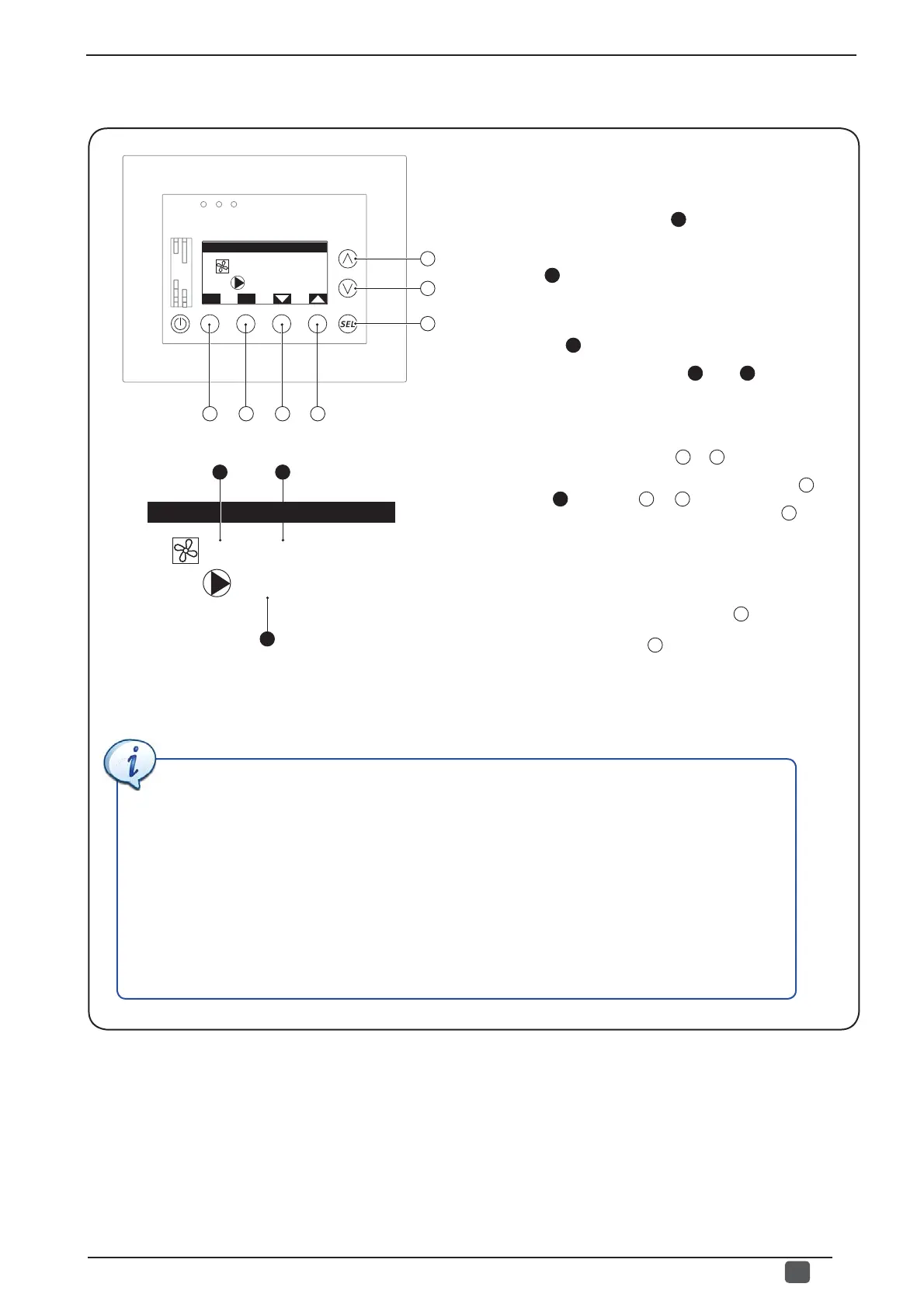
To manage activation of the pumps, they must be associated to
the master fan coils of the zone they serve;
this window displays
the following information:
- Index of the zone of reference (
1
): indicates which zone
(and therefore which master fan coil) the currently displayed
data refers to.
- Zone label (
2
): indicates the label (set by the user on the
last page of the fan coil menu; for further information, see the
VMF-E5 panel user manual) associated to the master fan coil
which the currently displayed data refers to.
- Pump number (
3
): if the system foresees its management,
the indicates which pump must be associated to the master
fan coil currently displayed in points
(
1
) and (
2
)
.
From this window it is possible to:
(1) Associate a specifi c pump to a master fan coil: this operation
consists in two distinct operations:
• Select the master fan coil, using the
E
or
D
key to browse the
master fan coils currently installed on the system;
• Select a pump to associate to the selected fan coil, press
C
to
select the fi eld (
3
), press the
A
or
B
key to select the pump
number to be associated and fi nally confi rm by pressing
C
once
again.
Naturally these two procedures must be performed for ALL master
fan coils of the system in order to make sure that each zone is
associated to a pump.
(2) Go back to the previous window: to go back to the
previous window of this menu, press the key
A
.
(3) Exit this window:
press the
G
key to return to the selection
of the menus.
• Associate each fan coil to its own pump
In the proposed example, the system has 4 pumps which must serve:
- 2 Night zones (named: Night A and Night B);
- 3 day zones (named: Bathroom, Kitchen, Day).
However keep in mind that the night zones (in the example served by master fan coils 1 and 2), must
be managed by one pump and therefore both masters must be associated to the same pump (in our
example, pump 1); while each of the other zones will be associated to a specifi c pump; to summarise,
the setting of the example system will be:
MASTER fan coil 01: NIGHT A= Pump 01;
MASTER fan coil 02: NIGHT B= Pump 01;
MASTER fan coil 03: BATHROOM= Pump 02;
MASTER fan coil 04: KITCHEN= Pump 03;
MASTER fan coil 05: DAY= Pump 04.
A
B
C
G
Configuration pumps
ESC
01
01:NOTTE A
F E D
3
Configuration pumps
01
01:NOTTE A
1 2