11
GB
6795773_01
Sequence of operations to be performed to install the various components:
(1) Install the selected heat pump; the unit must be appropriately installed electrically and hydraulically according
to that described in the system design. The heat pump is connected to the MODBUS serial line by means of the
MODU-485A accessory (see the relevant documentation to install this accessory).
(2) Install the system storage tank; the system storage tank must be installed according to standards in force,
making sure all the components required for its correct use are supplied (loading unit, pressure gauge, safety
valves, etc...).
(3) Install the DHW storage tank; the DHW storage tank must also be installed according to standards in force,
making sure all the components required for its correct use are supplied (loading unit, pressure gauge, safety
valves, etc...); remember to pay the utmost attention when selecting the supplementary electric resistance, the
size of which is linked to the dimension of the tank itself (the supplementary resistance will also affect the type of
electric control board to be purchased).
(4) Install the supplementary electric resistance for DHW storage tank; the DHW storage tank must be provided
with a 3kW single-phase supplementary electric resistance with relative safety thermostat, to be used in some
phases of domestic hot water production (for example during the anti-legionella cycle). The resistance must be
installed on the storage tank, According to the procedures indicated on the relevant documentation; the resistance
power supply must be connected to the specifi c terminals on the VMF-ACS3KTM accessory (as indicated in the
VMF-ACS board installation procedure).
(5) Install the 3-way diverter valve; this valve allows the VMF system to divert water from the air-conditioning
system to the DHW storage tank; this valve must be installed on the heat pump fl ow line, upstream the storage
tanks (as highlighted in the VMF system hydraulic diagram) connecting it to the VMF-ACS3KTM control board (as
indicated in the VMF-ACS control board installation procedure, provided further on).
(6) Install the VMF-ACS3KTM accessory; this accessory allows to manage the loads involved in domestic hot
water production, based on the intended type of system; in the proposed example the accessory will manage:
- The probe inserted in the system storage tank;
- The probe inserted in the DHW storage tank;
- The 3-way diverter valve;
- The electric resistance (3kW single-phase) inserted in the DHW storage tank.
To install the VMF-ACS electric control board, refer to the specifi c documentation.
(7) Install the VMF-CRP expansion board (1); this expansion board manages different types of loads; in this case
it will manage the heat recovery unit and the VMF-VOC accessory.
(8) Install the VMF-CRP expansion board (2); this expansion board manages different types of loads; in this
case it will manage the 4 zone pumps. The installation of the two VMF-CRP expansion boards requires appropriate
positioning in a specifi c electric box inside the technical room. The electric box, the fi xing brackets, the transformer
powering the VMF-CRP modules and all the protective elements necessary are not supplied. For further information
concerning assembly of the VMF-CRP modules, refer to the specifi c documentation.
(9) Install a collector with relative zone pumps; this element allows to manage the hydraulic lines and the pumps
of each individual zone from a point located in the technical room, as indicated in the standard hydraulic diagram
in the chapter “Hydraulic diagram of VMF system”.
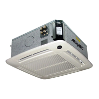
(10) Install the heat recovery unit; the UR unit provides an air exchange in the various rooms. For further
information concerning assembly of the heat recovery unit, refer to the specifi c documentation.
(11) Install the VMF-VOC probe; the accessory VMF-VOC probe detects air quality and therefore pilots a
heat recovery unit. For further information concerning assembly of the heat recovery unit, refer to the specifi c
documentation.