45
SWP_5287500_00
8. INSTALLATION
8.1. PRELIMINARY PROCEDURES
• Make sure the various unit
components are all intact.
• Make sure the various unit
components are all intact.
• Move the packaged section as near
as possible to the installation site.
• Do not stand equipment or weights on
top of the packaged unit.
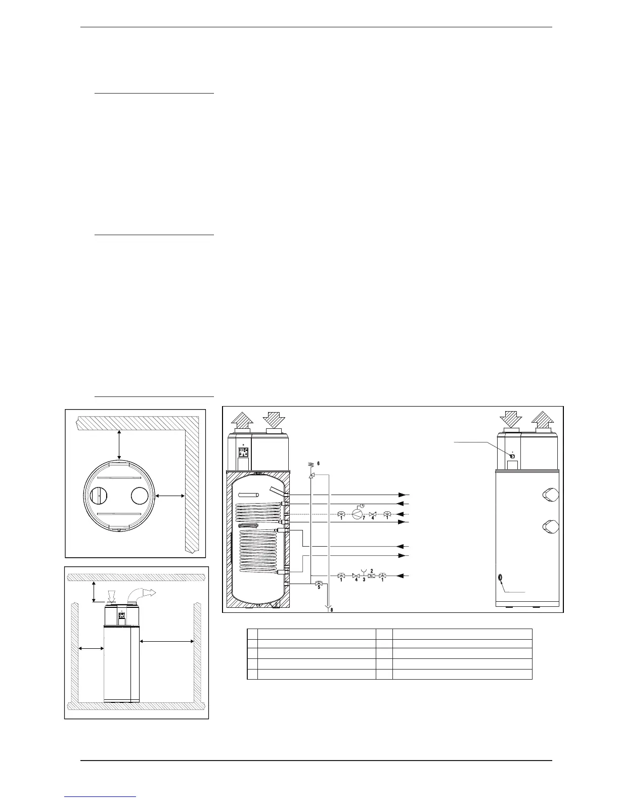
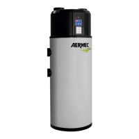
8.2. CHOOSING AN
INSTALLATION SITE
• On a fl at surface, the unit can
support the weight of the product
and its contents.
• Do not place the unit in areas
where fl ammable gases or acidic,
aggressive and corrosive substances
are present, as these could damage
the various components beyond
repair.
• If the unit is ducted, do not exceed
a total length of 10 metres.
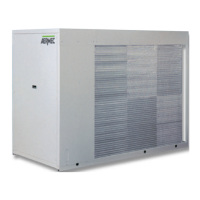
8.3. HYDRAULIC CONNECTIONS
Perform connection to the system
piping, so that the pipes:
• Are not resting their entire weight on
the unit.
• Allow maintenance procedures to
be carried out on the unit.
• Allow access and removal of any
accessories installed.
Make sure the tank can be emptied
without being de-pressurised; use a
vacuum breaker valve if necessary. The
operating pressure of the boilers is 6 bar.
For correct commissioning, we
recommend:
• The installation of a safety valve and
a suitably-sized expansion tank.
• Connection of the sacrifi cial anode
(supplied) to the metal bulk.
• Testing the hardness of the mains
water (the warranty will not be valid
for hardness levels under 15°F and
over 40°F).
1 Rolling shutter 6 Membrane safety valve
2 Pressure reducer 7 Circulation pump
3 Control valve 8 Drain
4 Non-return valve * PWW and PEP models only
5 Drain valve * * PEP models only
min. 0,5 m
min. 0,5 m
min. 0,3 m
min. 0,3 m
min. 1,2 m
hot water
heating delive
ry**
circulation (if necessary)
heating return
**
power
supply
alternative energy delivery
*
alternative energy
return
*
condensate
drain
cold water (connection
compliant with DIN 1988)
min. 0.5 m
min. 0.5 m
min. 0.3 m
min. 0.3 m
min. 1.2 m