Do you have a question about the AERMEC SWP200 and is the answer not in the manual?
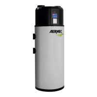
Identifies the heat pump unit and its purpose.
Instructions for keeping the manual with the appliance.
Essential safety precautions for using electrical and water products.
Explains how the SWP heat pump produces domestic hot water.
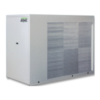
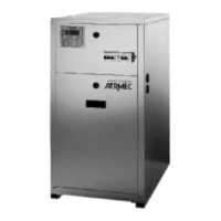
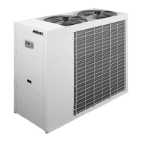
Details the physical build and materials of the SWP unit.
Describes the electrical control aspects and functions of the SWP.
Outlines different available configurations for the SWP module.
Provides detailed dimensional data and weights for different models.
Illustrates various use cases and installation scenarios for the SWP.
Explains airflow control via a motorised shutter system.
Covers procedures for safe packaging of the unit.
Instructions for safe handling and movement of the unit.
Steps to verify the unit's condition upon delivery.
Recommendations for proper storage of the unit.
Essential steps before commencing the installation process.
Criteria for choosing an appropriate location for the unit.
Details on how to make the necessary water pipe connections.
Instructions for connecting the condensate drainage system.
Guidelines for air duct connections if required.
Procedures for safe and correct electrical hook-up.
Explains the operational logic of the temperature controller.
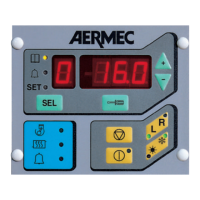
Describes the layout and components of the user interface.
Details the display segments and functionality of the control buttons.
Lists and explains the functions of PCB digital inputs and relay outputs.
Visual representation of the Printed Circuit Board layout and connections.
Guides on adjusting user and manufacturer parameters.
Instructions on how to view machine status and parameters.
Explains how the controller manages temperature using HP and heating element.
Describes the state when the machine is powered off.
Details the standby operating status and its functions.
Explains the automatic mode of operation for the heat pump.
Describes manual operation using only the electric heating element.
Procedures for activating and managing the anti-bacterial function.
Explains the unit's ability to restart after a power interruption.
Details how the set point adjusts based on outside air temperature.
Overview diagram of automatic operation parameter flow.
Table listing user-configurable parameters.
Visual representation of user parameter navigation.
Table of manufacturer and configuration parameters.
Visual flow of manufacturer and configuration parameter settings.
Diagram illustrating manufacturer alarm parameters.
Table of manufacturer-specific alarm parameters.
Explains the meaning and intervention of various alarm codes.
Procedures for regular maintenance tasks.
Specific checks to perform on a quarterly basis.
Annual maintenance and checks before initial operation.
Table of common problems and their possible causes and solutions.
Guidelines for environmentally responsible disposal of the unit.