48
SWP_5287500_00
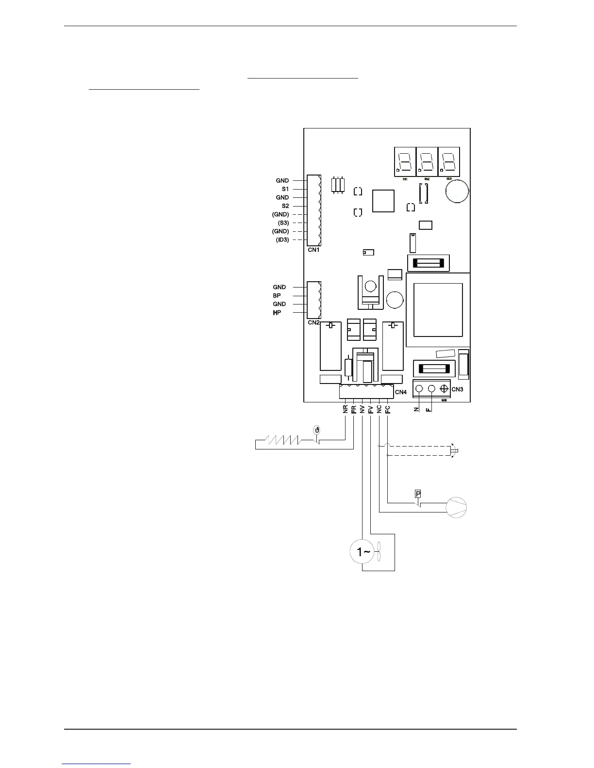
10. PCB
10.1. DESCRIPTION OF PCB INPUTS/
OUTPUTS
DIGITAL INPUTS:
HP= high pressure
BP= low pressure
(ID3)= ANALOGUE INPUT provision
only:
S1= water probe
S2= air probe
(S3= input provision only)
RELAY OUTPUTS:
NR,FR= heating element activation
consent
NV,FC= fan activation consent
NC,FC= compressor activation
consent (and, in parallel,
any servocontrol for D160S
distributor)
10.2. PCB DIAGRAM
water probe
internal air probe
optional air probe
heating element
fan
compressor
(any servocontrol for D160S)
power supply