Do you have a question about the AERMEC SWP300 S1 and is the answer not in the manual?
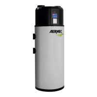
Identifies the SWP heat pump, its intended use, and instructions for storing the manual.
Essential safety rules for using products requiring electricity and water, emphasizing caution with wet bodies and disconnections.
Explains how the SWP heat pump extracts heat from the air to heat domestic water.
Details the physical construction aspects of the SWP unit, including tank, insulation, and materials.
Describes the electrical control features, including set point adjustment, self-diagnosis, and parameter settings.
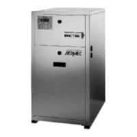
Details the available configurations for the SWP module, adapting to various system requirements.
Provides detailed physical dimensions and weights for different SWP models, including diagrams.
Illustrates various installation scenarios and uses for the SWP heat pump in different domestic settings.
Explains how a motorised shutter controls airflow for ventilation, linked to fan status.
Covers packaging, handling, checks on receipt, and storage recommendations for heat pumps.
Steps to take before installation, ensuring component integrity and proper positioning of the unit.
Criteria for selecting a suitable installation location, considering weight support and environmental factors.
Details on making hydraulic connections, ensuring proper pipe support and access for maintenance.
Instructions for connecting the condensate drain hose and installing aeraulic ducts.
Critical steps for electrical connection, emphasizing safety switches, voltage checks, and proper wiring.
Explains how the controller manages temperature regulation, operating modes, and alarms.
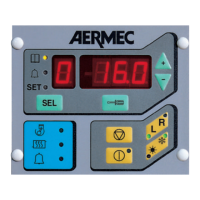
Details the physical layout of the controller's user interface, including buttons and LEDs.
Describes the information displayed on the 7-segment display, such as temperature, alarms, and operating hours.
Explains the function of each button ([ON/OFF], [SET], [A/M], Anti-bacterial) on the controller interface.
Lists and defines the digital inputs, analogue inputs, and relay outputs on the Printed Circuit Board.
Provides a schematic diagram of the Printed Circuit Board, showing connections for components and inputs/outputs.
Guide to accessing and modifying user and manufacturer parameters using the controller buttons.
Instructions for viewing machine status information and parameters without making changes.
Explains how the controller regulates temperature using the heat pump and electric element based on sensors.
Describes the 'Machine Off' status, where the unit is powered but inactive, with alarms still active.
Explains the Standby mode, how to enter it, and its relation to other operating modes.
Details the automatic operation mode, including heat pump activation conditions, fan modulation, and status indicators.
Describes manual operation where only the electric heating element is active, useful for reducing transition periods.
Explains the anti-bacterial cycle, its purpose, activation, and related parameters for thermal shock.
Describes the Autostart function, which allows the unit to restart automatically after a power interruption.
Explains how the dynamic set point function automatically adjusts the set point based on outside air temperature.
Provides a general flowchart diagram illustrating the control logic and parameter adjustments in automatic operation.
Lists user parameters (U01, U02) with default values, limits, and descriptions for boiler water set points.
Illustrates the user interface navigation for modifying user parameters, specifically boiler water set points.
Lists manufacturer parameters (H01-H36) with default values, limits, and descriptions.
Depicts the navigation path for manufacturer/configuration parameters, covering various settings like set points and differentials.
Visual representation of the navigation path for manufacturer/alarm parameters.
Details essential checks required before activating the unit and outlines maintenance procedures.
Addresses common causes and solutions for when the heat pump fails to start or its compressor/fan do not operate.
Explains potential causes for repeated start/stop cycles or continuous operation without stopping.
Details troubleshooting steps for when the electric heating element fails to activate.