10
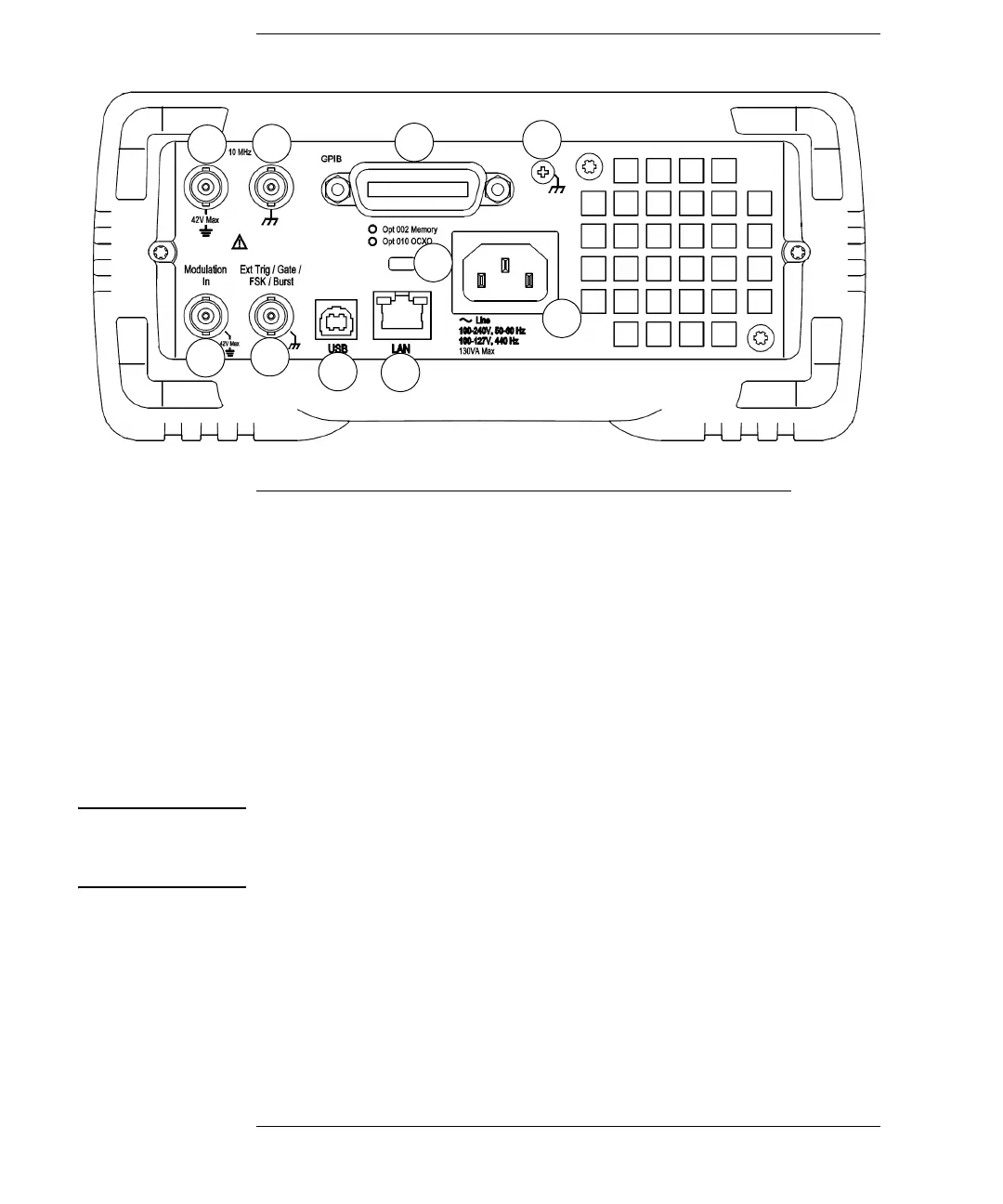
The Rear Panel at a Glance
WARNING For protection from electrical shock, the power cord ground must not be
defeated. If only a two-contact electrical outlet is available, connect the
instrument’s chassis ground screw (see above) to a good earth ground.
1 External 10 MHz Reference Input Terminal
2 Internal 10 MHz Reference Output Terminal
3 GPIB Interface Connector (option 400)
4 Chassis Ground
5 External Modulation Input Terminal
6 Input: External Trig/Gate/FSK/Burst
7 USB Interface Connector
8 Local Area Network (LAN) Connector
9 Instrument Cable Lock
10 AC Power
 Loading...