97
Chapter 4 Calibration and Adjustment
AC Amplitude (high-impedance) Verification
4
AC Amplitude (high-impedance) Verification
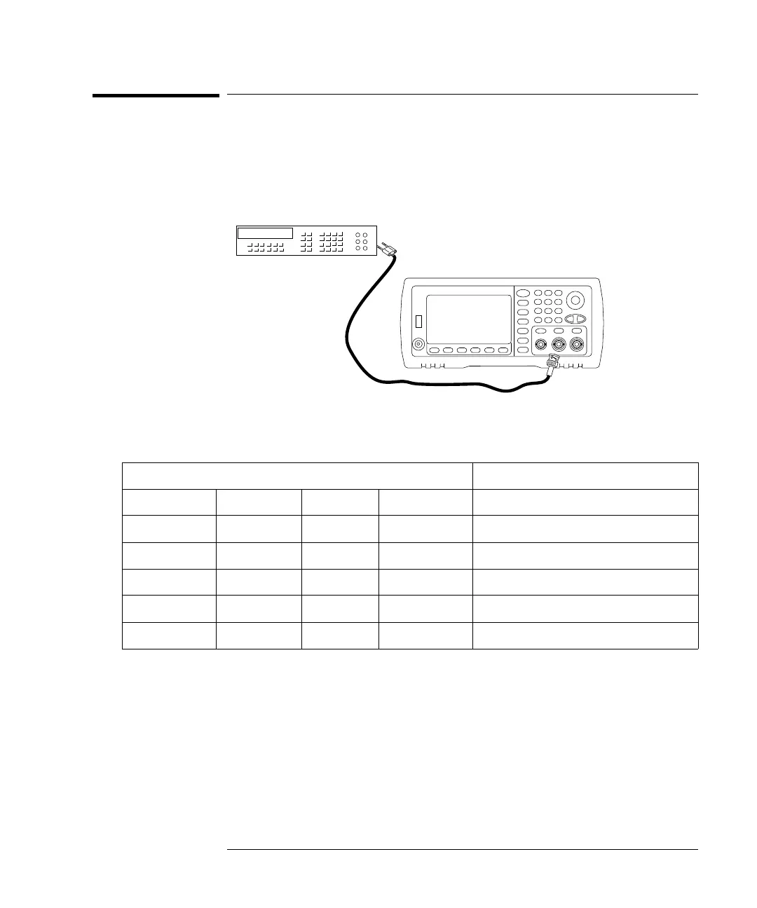
This procedure checks the ac amplitude output accuracy at a frequency
of 1 kHz using each attenuator.
1 Set the DMM to measure Vrms. Connect the DMM to the channel 1
output as shown below.
2 Set the instrument to each output described in the table below and
measure the output voltage with the DMM. Be sure the output
impedance is set to High–Z and the output is enabled.
* Based upon 1% of setting ±1 mVpp (50 ); converted to Vrms for High–Z.
**
Use the following sequence to set this output:
a Set the amplitude to 400.0 mVrms
b Set the DC Offset to 1.0 Vdc
c Set Auto-Range to OFF
d Set DC Offset Voltage to 0.0 Vdc
e After the measurement, set Auto-Range to ON for the rest of the measurements.
3 Compare the measured voltage to the test limits shown in the table.
4 33522A Only. Connect the DMM to the channel 2 output and repeat
steps 2 and 3.
Waveform Generator Measurement
Output Setup Function Frequency Amplitude Nominal Error*
Q High Z** Sine Wave 1.000 kHz 400.0 mVrms 0.400 Vrms ± 0.004707 Vrms
Q High Z Sine Wave 1.000 kHz 400.0 mVrms 0.400 Vrms ± 0.004707 Vrms
Q High Z Sine Wave 1.000 kHz 1.00 Vrms 1.00 Vrms ± 0.010707 Vrms
Q High Z Sine Wave 1.000 kHz 2.500 Vrms 2.5 Vrms ± 0.025707 Vrms
Q High Z Sine Wave 1.000 kHz 7.000 Vrms 7.0000 Vrms ± 0.070707 Vrms

 Loading...