114
Chapter 4 Calibration and Adjustment
AC Amplitude (high-impedance) Adjustment
4
AC Amplitude (high-impedance) Adjustment
The waveform generator stores a calibration constant for each high-
impedance attenuator path. The gain coefficient of each path is
calculated using two measurements; one with the waveform DAC at +
output and one with waveform DAC at – output. The setups, therefore,
must be performed in pairs.
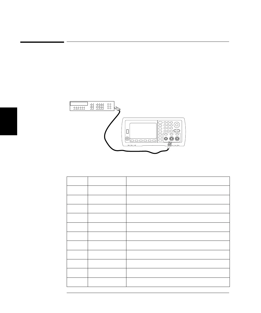
1 Connect the DMM to the Channel 1 Output as shown below.
2 Use the DMM to measure the dc voltage at the front-panel Output
connector for each setup in the following table.
Nominal Signal
Setup DC level
10 +0.0028 V Output of -72 dB range
11* -0.0028 V Output of -72 dB range
12 +0.007 V Output of -64 dB range
13* -0.007 V Output of -64 dB range
14 +0.017 V Output of -56 dB range
15* -0.017 V Output of -56 dB range
16 +0.044 V Output of -48 dB range
17* -0.04 V Output of -48 dB range
18 +0.11 V Output of -40 dB range
19* -0.11 V Output of -40 dB range
 Loading...