162
Chapter 6 Service and Repair
Disassembly
6
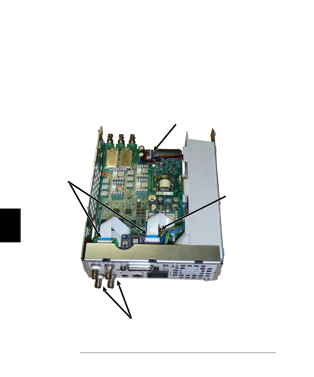
3 Removing the Main Board. Disconnect the power supply connector from
the main board. Disconnect the GPIB and Oscillator In ribbon cables.
Disconnect the fan power cable from the main board. Loosen and remove
the nuts securing the Modulation In and Ext Trigger BNC connector to
the rear panel. Remove the screw below the GPIB board securing the
main board to the chassis. Slide the main board toward the front of the
instrument to disengage the tabs on the power supply cover. Lift the
main board out.
Fan
Connector
Power Supply
Connector
Ribbon
Cables
BNC Nut
& Lockwasher

 Loading...