22
Chapter 1 Specifications
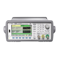
Agilent 33500 Series Function / Arbitrary Waveform Generator
1
SYNC / MARKER OUTPUT
Connector Front-panel BNC, isolated from
chassis
Functions Sync, Sweep Marker, Burst
Marker, or Arbitrary Waveform
Marker
Assignment Channel 1 or Channel 2
Polarity Normal or Inverted
Voltage Level
(nom)
3 Vpp into open circuit, 1.5 Vpp
into 50 Ω
Output
Impedance
(nom)
50 Ω
Min. Pulse
Width (nom)
16 ns
MODULATION INPUT
Connector Rear-panel BNC, isolated
Assignment Channel 1, Channel 2, or Both
Voltage Level ±5 V full-scale
Input
Impedance
(nom)
5 kΩ
Bandwidth (-3
dB typ)
DC to 100 kHz
FREQUENCY REFERENCE INPUT
Connector Rear-panel BNC, isolated from
chassis and all other connectors
Reference
Selection
Internal, External, or Auto
Frequency
Range
Standard: 10 MHz ± 20 Hz
Option 010: 10 MHz ± 1 Hz
Lock Time (typ) <2 s
Voltage Level 200 mVpp to 5 Vpp
Input
Impedance
(nom)
1 kΩ || 20 pF, AC-coupled
FREQUENCY REFERENCE OUTPUT
Connector Rear-panel BNC, chassis-
referenced
Output
Impedance
(nom)
50 Ω, AC-coupled
Level (nom) 0 dBm, 632 mVpp
REAL-TIME CLOCK / CALENDAR
Set and Read Year, Month, Day, Hour, Minute,
Second
Battery CR-2032 coin-type, replaceable,
>5-year life (typ)
 Loading...


